Skip to step 15, 9 through 15 – Grass Valley VM 3000 System Controllers v.7.4 User Manual
Page 280
Configurator
CP Input Set
5−70
VM 3000 Installation and Operating Manual
14.
GVG 200 − E−MEM
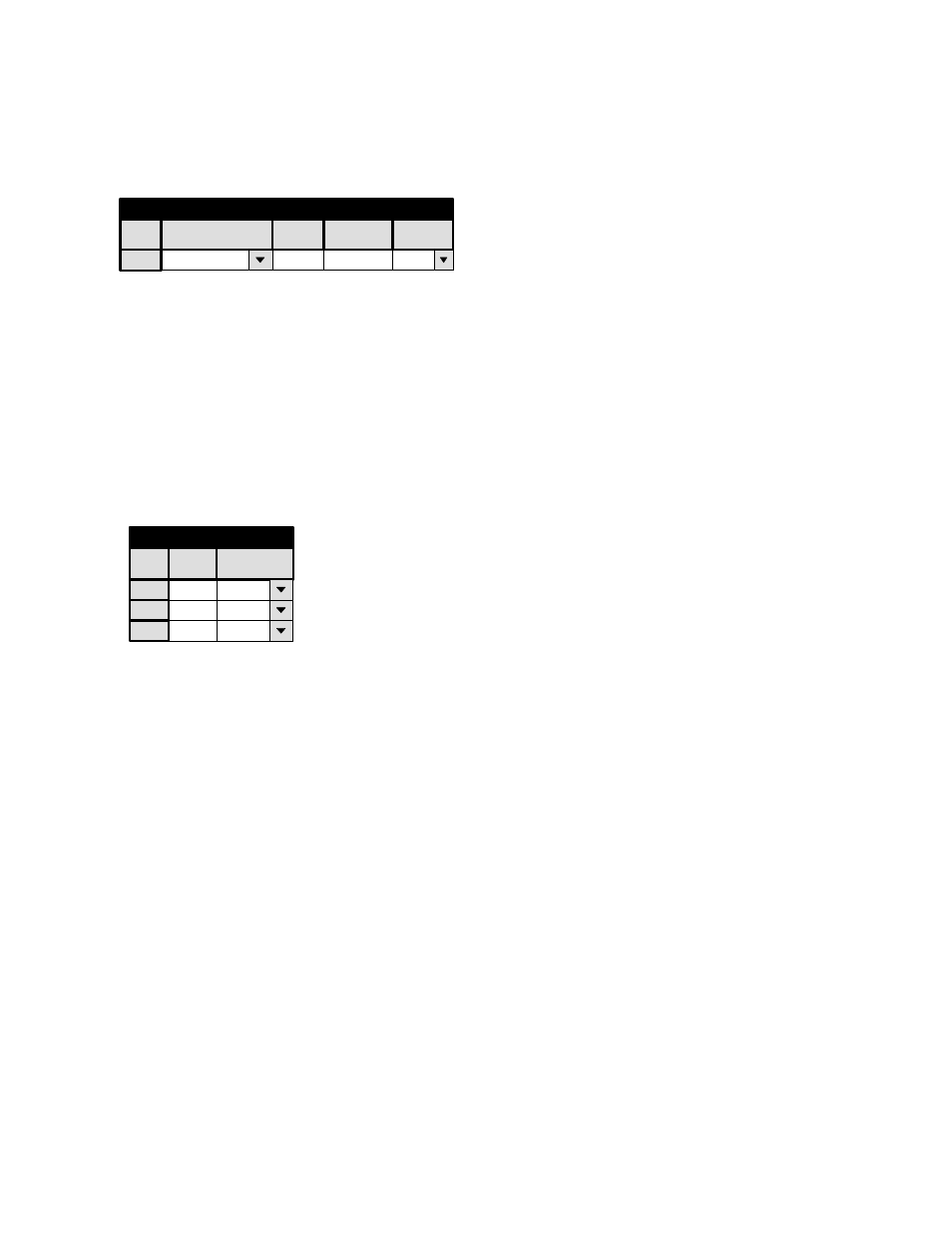
If you are entering a set for GVG 200 E−MEM, you will need a table similar to that shown in Figure 5−49.
Figure 5−49. Input Set menu (example).
1
Input Set — KXYZ−INP
Category
Entry
Mnemonic
Input
dflt
0
BARS
BARS
Logical
The entries on this table are not actually used, but the table must exist for the sake of having a set name on the MPK
devices table (page 5−130) in order to satisfy the compiler. Therefore, the table can consist of a single row with Category
“dflt,” Entry “0,” and the name of a valid input.
When finished, skip to Step 17.
15.
Philips Broadcast Automation / External Computer
If you are entering a set for serial control device, a menu similar to that shown in Figure 5−50 will appear.
Figure 5−50. Serial Input Set menu.
1
Input Set — PC−INP
2
1
2
Entry
CAM1
CAM2
Input
3
3
VTR1
Logical
The purpose of the table is to establish a unique “Entry” number for each switcher “Input” name. In Figure 5−50, Entry
number “1” is associated with Input name “CAM1.” The Entry number is the number that the serial control device must
send to Jupiter. When the Entry number arrives, the software checks this table to find the associated Input name; then
the Switcher Inputs table (page 5−44) is checked to find the corresponding physical input number.
Note: For Philips Broadcast Automation systems, it is suggested that you print out this Input Set; you will
need this information when setting up the Automation Switcher Initialization menu. The input names entered
on the Jupiter Input Set table must be in the same order as they are on the Automation table. Any changes
made to one table must also be made to the other.