Philips broadcast automation systems – Grass Valley VM 3000 System Controllers v.7.4 User Manual
Page 155

Hardware Installation
2−83
VM 3000 Installation and Operating Manual
Philips Broadcast Automation Systems
Note: This discussion applies to router control only. For information about connections to a Saturn Master Control
switcher, please refer to the Saturn Installation and Operating manual.
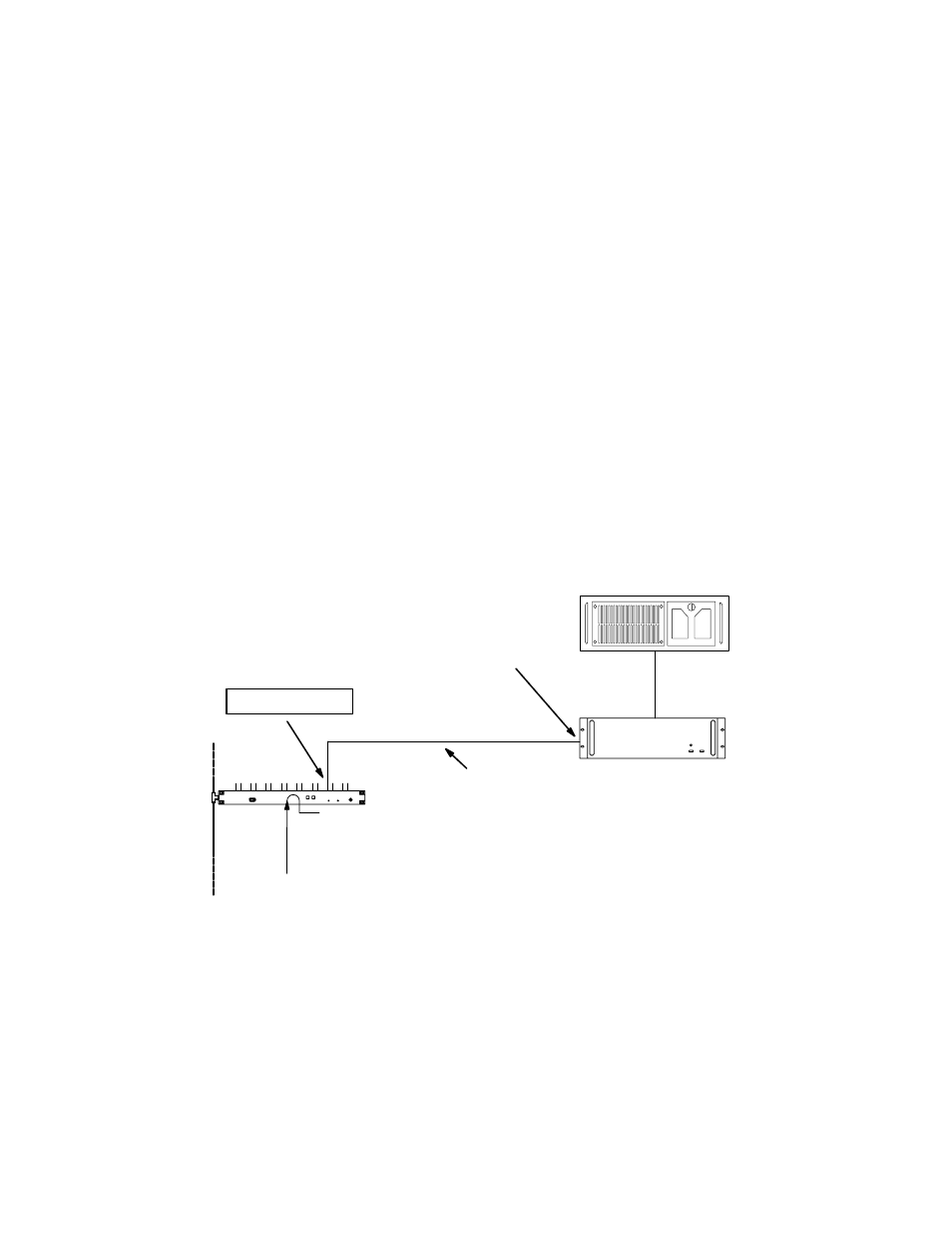
Hardware connections are shown in Figure 2−97.
A ready−made cable, with installed 9−pin D and RJ45 male connectors, is available from Grass Valley. For those who wish
to prepare their own cable, the pin−outs are shown on page 2−84. The cable itself should be Belden 8723 or equivalent.
Within the Philips Automation MSL 4000 Server, the IFS 4 interface board will require a “BV” type PROM installed for the
port that is connected to the VM/SI. For more information, refer to the installation instructions supplied with the MSL 4000.
For the VM/SI 3000, “ESswitch” protocol must be set on the Serial Protocol table (page 5−25). The baud rate must be set
to match that being used by the IFS 4 port of the MSL 4000 (usually 9600).
The MSL 4000 Remote Program Controller is identified on the MPK Devices table (page 5−128). The MSL 4000 can use
the same CP Level Set (type “CP3000”) that all the control panels use as long as the levels the Automation system needs to
control are defined. CP Level Sets are discussed in detail starting on page 5−55. The MSL 4000 uses a “Serial” type CP Input
Set (page 5−58) and a “Serial” type CP Output Set (page 5−76).
VM/SI 3000
ESswitch protocol
LAN cable
Sync ref. See
See Figure 2−98 for a
description of this cable
“MSL4000”
“SI3”
Philips Automation
computer
MSL 4000 Server
For ESswitch protocol, use
odd−numbered ports only
IFS 4 interface
board port
Automation LAN
Figure 2−97. Connections for router control.
