Grass Valley VM 3000 System Controllers v.7.4 User Manual
Page 177
Hardware Installation
2−105
VM 3000 Installation and Operating Manual
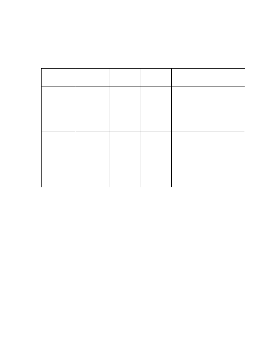
The 40 output connections can be used with various numbers of control panels and functions, depending on how the system
software is configured by the user. The three possible configurations are shown in Figure 2−119; the back−panel connections
for these configurations are shown in Figure 2−120.
Configuration
Max. number
Functions
Names
of MC 3040
of control panels
per panel
of functions
Notes
MC 3040/2
20
2
Play
Stop
MC 3040/4
10
4
Play
Stop
Ready
Cue
MC 3040/8
5
8
Play
Stop
Ready
Cue
Fast forward
(shuttle with positive velocity)
Rewind
(shuttle with negative velocity)
Set mark
Record
Figure 2−119. MC 3040 configurations.
Important: MC 3040 function number four (“Cue”) and function number eight (“Record”) are reversed from
their positions in the original MI 3040. This difference can be seen by comparing Figure 2−119 with Figure 2−115
on page 2−101.
Note: While the user can select any one of the configurations, the particular transport functions within each con-
figuration, and the order in which they appear on the MC−3040 back panel, cannot be changed by the user.
An example of the connections for a unit configured as an MC 3040/2 is shown in Figure 2−121.
Important:: Because the MC 3040 hardware is the same as the MI 3040, the rear−panel labelling is misleading.
The “Status In” connectors are actually used to receive commands from the control device, while the “Relay Con-
tacts” connectors are used to provide status.
The configuration of the MC 3040 is determined by entries to the MPK devices table (page 5−118) and the Machine Control
Devices table (page 5−157) .