Party line levels – Grass Valley VM 3000 System Controllers v.7.4 User Manual
Page 379
Configurator
Party Line
5−169
VM 3000 Installation and Operating Manual
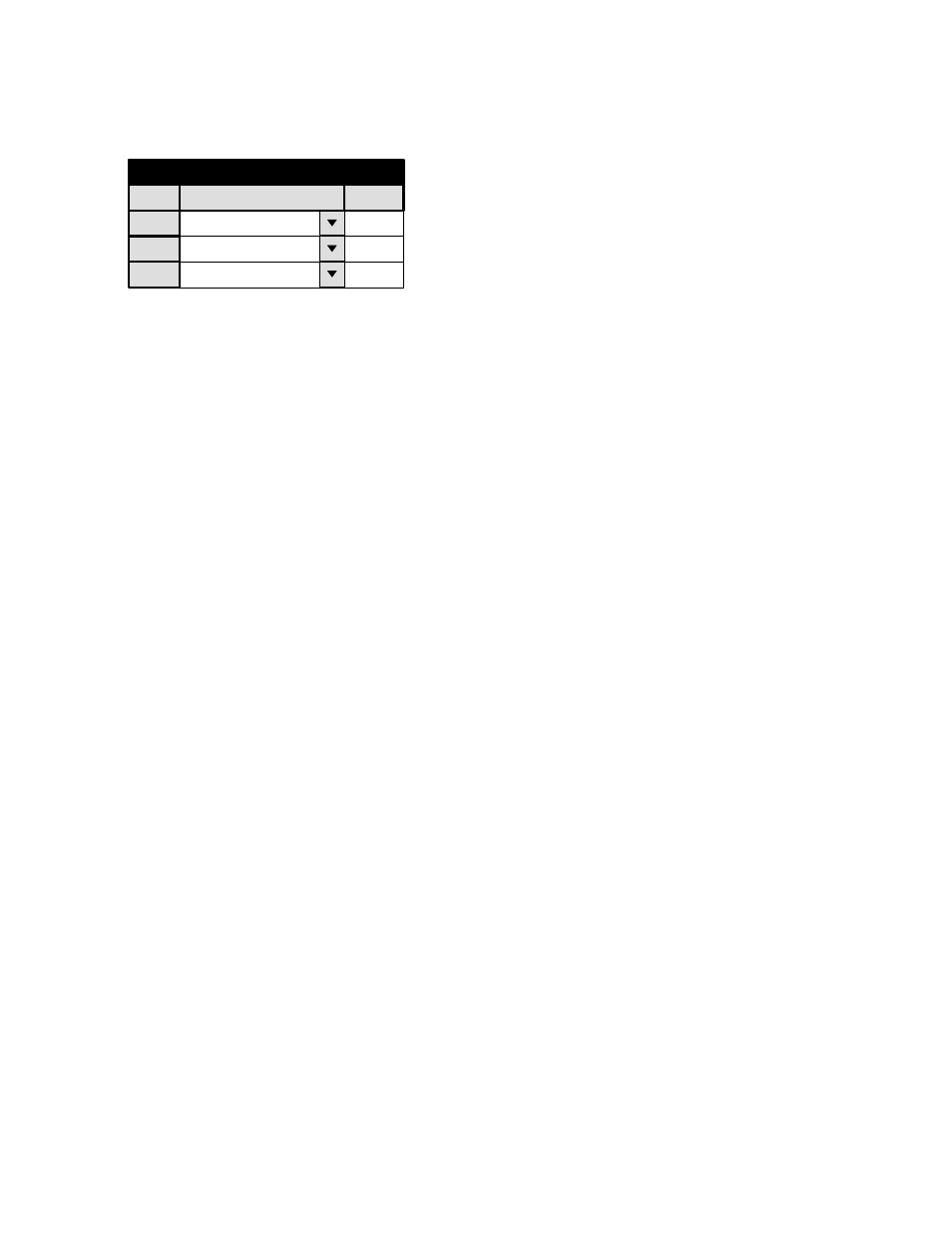
PARTY LINE LEVELS
1
Party Line Levels
Level
VIDEO (MAINROUT)
PLevel
1
2
LEFT (MAINROUT)
2
3
RIGHT (MAINROUT)
4
Figure 5−148. Party line levels menu (example).
This menu must be used when party line−type control panels are installed in the system. This includes the MCS 2000 Master
Control switcher.
These panels are capable of controlling up to seven levels, whereas the Jupiter system itself can control 126 levels. Thus a
maximum of up to seven of the switcher levels can be selected for control by party line panels. Accordingly, this conversion
table lists up to seven party line level numbers, and for each of these, the name for the physical level (from the Switcher De-
scription menu, page 5−31).
If you are adding the Jupiter to an existing TVS/TAS 2000 system, you may wish to maintain the traditional party line level
numbers (as on Figure 5−148), but this is not necessary. For example, you may wish to have
Party line level 1
=
KXYZ VIDEO
=
Physical Level 1
Party line level 2
=
KXYZ LEFT
=
Physical Level 2
Party line level 4
=
KXYZ RIGHT
=
Physical Level 8
For the MCS 2000 Master Control switcher, party line level identification is established with the Setup mode, as described
in the MCS 2000 manual.