Grass valley ascii protocol, Serial (p. 5−128) – Grass Valley VM 3000 System Controllers v.7.4 User Manual
Page 338
Configurator
MPK Devices
5−128
VM 3000 Installation and Operating Manual
PHILIPS BROADCAST AUTOMATION SYSTEMS − SERIAL CONTROL
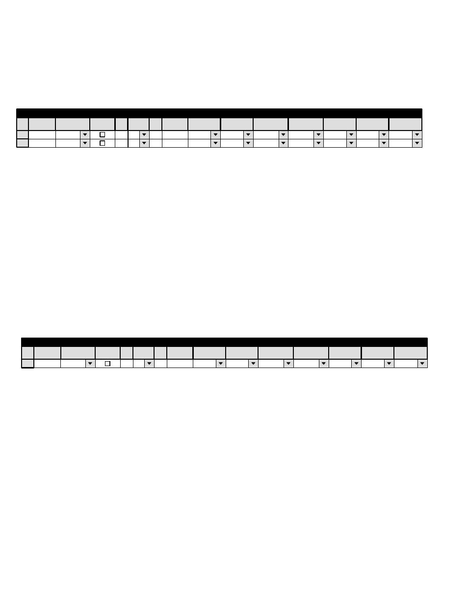
Hardware installation was discussed on page 2−83; serial port configuration was discussed on page 5−28. Figure 5−102 shows
an example table for the system on page 2−83. Note that no MPK address is required.
MSL4000
Serial
SI3
13
ALAM−INP
ALAM−OUT
1
MPK Devices
MPK
Expansion
Pass
Board
Port
Address
Input Sets
Output Sets
Level Set
Overide Set
Sequence Set
2
KXYZ−LEV
Devices
word
In Panel
Out Panel
Figure 5−102. Entry for automation system shown on page 2−83.
Device
Type
The MSL 4000 can use the same CP Level Set that all the control panels use as long as the levels the automation system needs
to control are defined. CP Level Sets are discussed in detail starting on page 5−55.
The MSL 4000 uses a “Serial” type CP Input Set (page 5−58) and a “Serial” type CP Output Set (page 5−76).
ENCORE OR CONTROL COMPUTERS USING “ESSWITCH” ROUTING SWITCHER DIALECT OR
GRASS VALLEY ASCII PROTOCOL
Encore installation was discussed on page 2−82. Serial port configuration was discussed on page 5−25 and following.
Control computer installation was discussed on page 2−85; serial port configuration was discussed on page 5−25. Figure
5−103 shows an example table for the system in Figure 2−99 on page 2−85. Note that no MPK address is required.
PC−OUT
SWITCHPC
SERIAL
SI3
9
PC−INP
KXYZ−LEV
1
MPK Devices
MPK
Expansion
Pass
Board
Port
Address
Input Sets
Output Sets
Level Set
Overide Set
Sequence Set
Devices
word
In Panel
Out Panel
Figure 5−103. Entry for system shown in Figure 2−99 on page 2−85.
Device
Type
The Input, Output, and Level Sets named on this table should include all inputs, outputs, and levels that will be controlled
by the external control device. As a precaution, you may wish to restrict computer control to selected outputs.
The Input (page 5−58) and Output (page 5−76) sets must be created specifically for use by “serial” devices.
The Level Set must be created as a type “CP−3000” (see page 5−55.) For an important note about level numbering and external
computer control, see page 5−57.