Party line tables, Party line description – Grass Valley VM 3000 System Controllers v.7.4 User Manual
Page 377
Configurator
Party Line
5−167
VM 3000 Installation and Operating Manual
Party Line Tables
Configuring the VM 3000 party line port
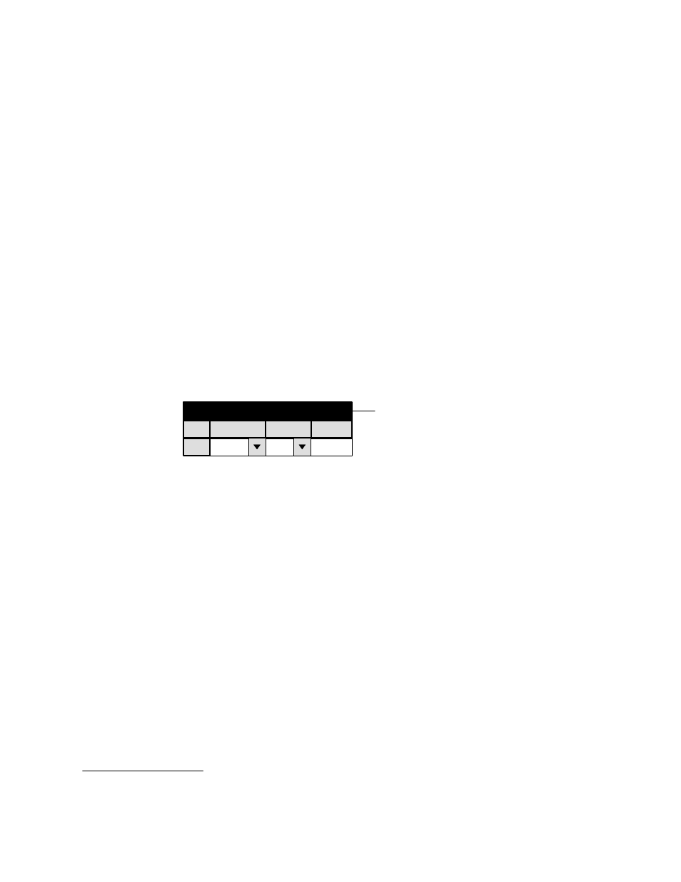
PARTY LINE DESCRIPTION
1
Party Line Description
Board
VM1
Type
Poll No.
S
112
Figure 5−146. Party Line Description table (example).
Switcher Description
Control Panel Sets
Machines
TCS−1 Device Codes
Status Display Header
Tally
Path Finding
Exclusion
This table must be used when the Party Line port of a VM 3000 is connected.
§
The source of the Board names is the Network
The entry for Type determines the protocol that will be generated by the VM 3000. Extended allows party line type panels
to control 250 inputs and 150 outputs; super allows such panels to control 250 inputs and 250 outputs. Most current party
line control panels will adjust automatically to either type. The usual setting is super.
The Polling Number is the lowest polling number for the party line control panels in the system. For example, if there are
three party line panels and their polling numbers are 120, 122, and 124, then the entry would be 120. The polling number for
each party line panel is set at the panel itself, either with internal DIP switches or, as is the case with the MCS−2000, by front−
panel programming. For more information, please refer to the manual supplied with the panel.
A detailed description of the party line, sample points, and polling numbers can be found in the CE 2200 Polling and Control
board section of the TVS/TAS 2000 Technical Manual.
§