Appendix c, Probe connections and protocol, Use of a probe cable is described in appendix c – Grass Valley VM 3000 System Controllers v.7.4 User Manual
Page 661: Figure c−1. location of probe connectors, Figure c−2. probe cable for all controller boards
C−1
VM 3000 Installation and Operating Manual
Appendix C
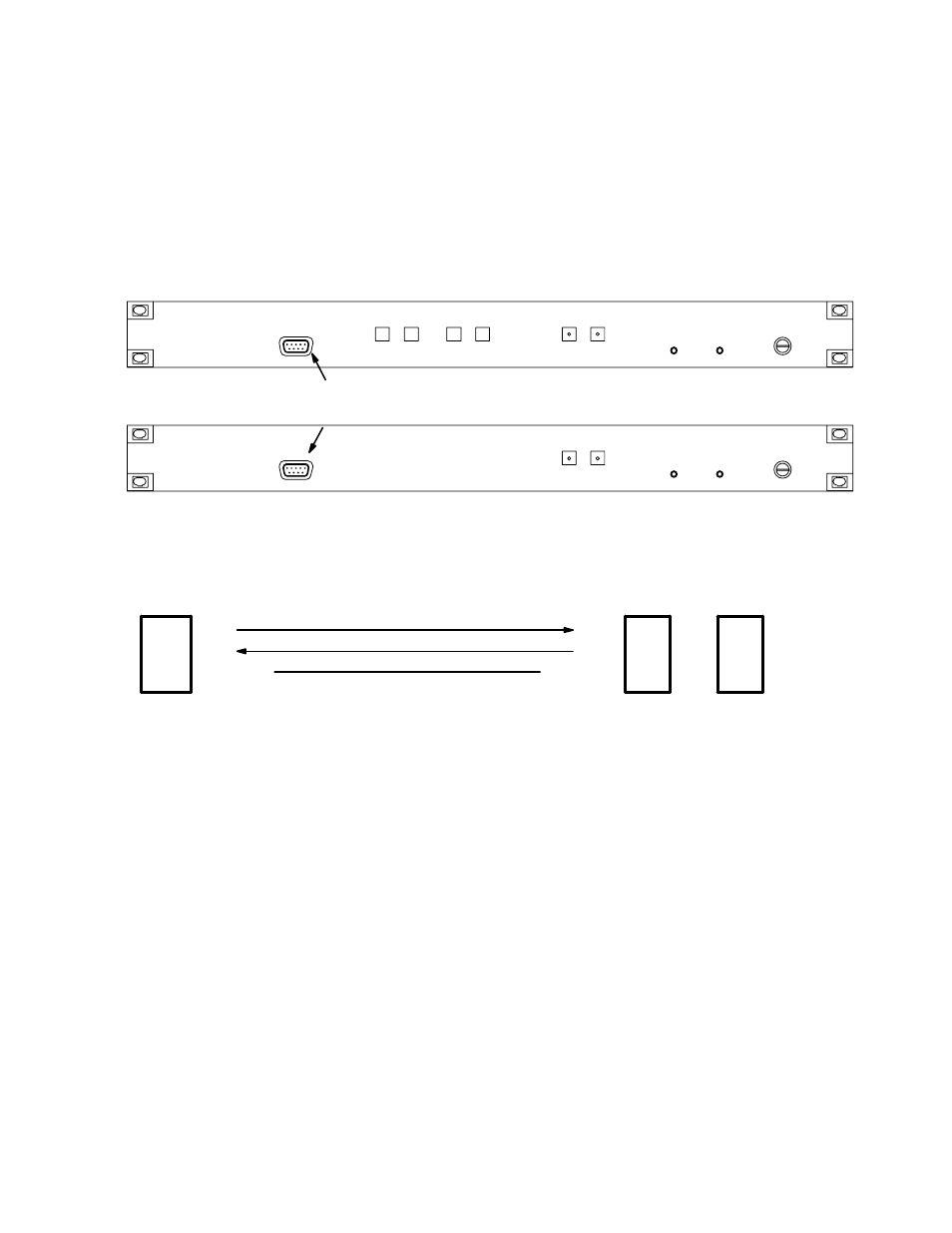
Probe Connections and Protocol
Figure C−1. Location of Probe connectors.
Probe
connector
VM 3000
SI 3000
UP
DOWN
NEXT
SELECT
ACTIVE
FAULT
FAULT
CLEAR
ACTIVATE
POWER
ALARM
PROBE
ACTIVE
FAULT
FAULT
CLEAR
ACTIVATE
POWER
ALARM
PROBE
Rxd
TxD
Signal Gnd
pin 2
pin 3
pin 5
Txd
Rxd
To controller board
Probe connector
Logic ground
DB9P (male)
To computer/terminal
DB25P connector
pin 3
pin 2
pin 7
DB9S connector
pin 2
pin 3
pin 5
OR
Figure C−2. Probe cable for all controller boards.
The Probe connection is provided for test purposes. The protocol for this port is 9600 baud, 8 data bits, 1 stop bit, no parity.
All boards can be reset by momentarily shorting pin 7 to pin 5 on the Probe port.
This manual is related to the following products: