Machine control table, Select “mc−3000 – Grass Valley VM 3000 System Controllers v.7.4 User Manual
Page 569
Software Control Panel Suite
7−5
VM 3000 Installation and Operating Manual
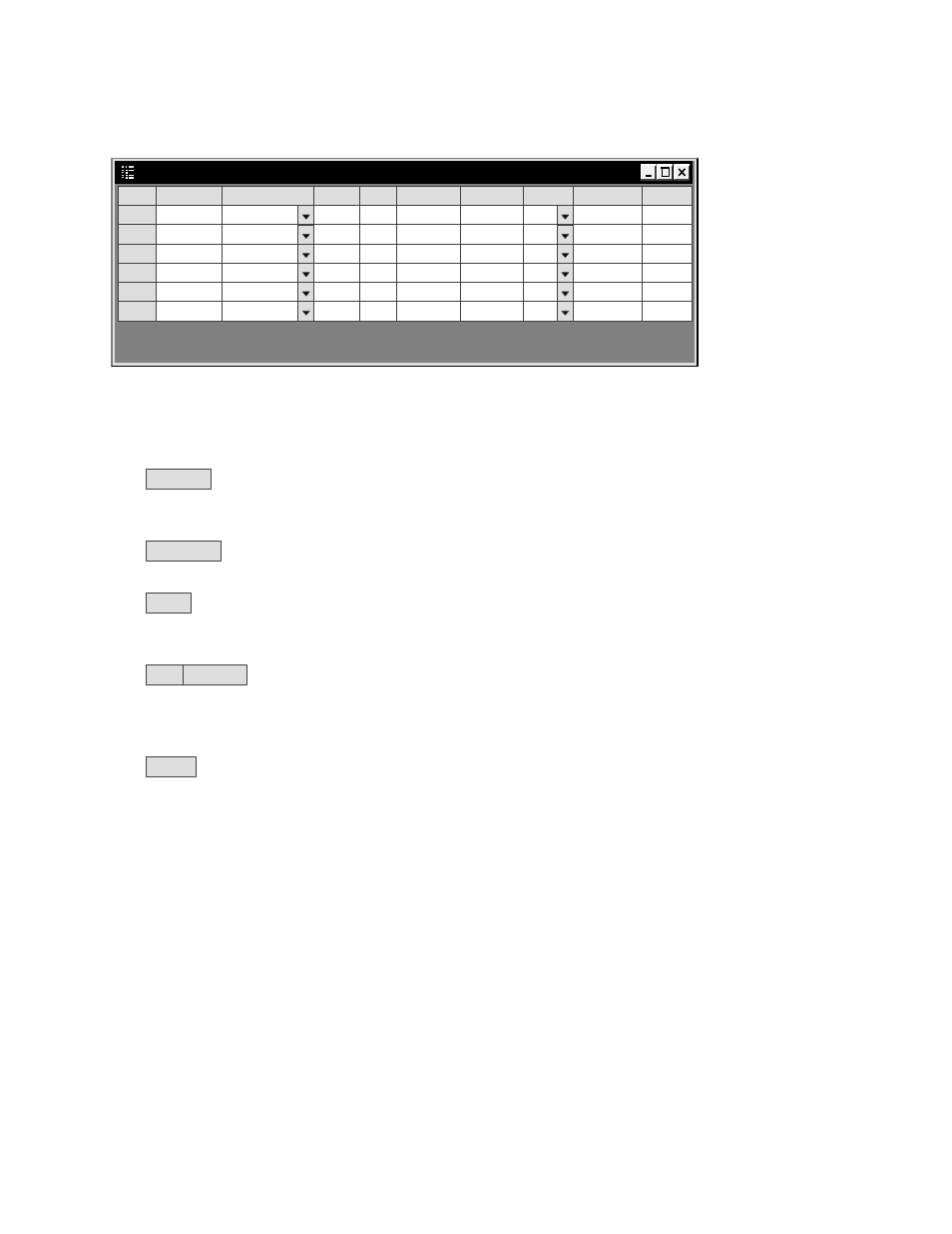
MACHINE CONTROL TABLE
Machine Control
1
Dev Name
PC1MC1
Dev Type
MC−3000
Board
PC1
Port
1
Address
01010101
Group
I/O
Asoc Name
Preroll
MC−3000
Out
2
PC1MC2
MC−3000
PC1
1
23232323
MC−3000
Out
3
PC1MC3
MC−3000
PC1
1
45454545
MC−3000
Out
4
PC1MC4
MC−3000
PC1
1
67676767
MC−3000
Out
5
PC1MC5
MC−3000
PC1
1
89898989
MC−3000
Out
6
PC1MC6
MC−3000
PC1
1
90909090
MC−3000
Out
Figure 7−4.
Dev Name
Enter the Device Name for each of the six Slaved Machine Control panels. These must agree
with the names entered on the MPK devices table.
Dev Type
Select “MC−3000.”
Board
Enter the Name of the PC that will display these panels. This must agree with the PC’s Board
Name entered on the Network Description table (page 7−1).
Port
Address
To satisfy the compiler, there must be a unique entry in these fields and this entry must
agree with the corresponding entry on the MPK table. In this example, “PC1MC1” has the Address
“01010101” on both tables.
I/O
Select “Out.”