Party line input and output – Grass Valley VM 3000 System Controllers v.7.4 User Manual
Page 378
Configurator
Party Line
5−168
VM 3000 Installation and Operating Manual
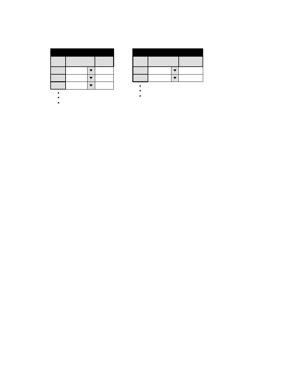
PARTY LINE INPUT AND OUTPUT
1
Party Line Output
Output
LINE
PLOutput
54
2
MCPS
55
Logical
1
Party Line Input
Input
BARS
PLInput
0
2
VT01
1
3
VT02
2
Logical
Figure 5−147. Party Line Input And Output tables (example).
These menus must be used when party line−type control panels are installed in the system. This includes the MCS 2000 Master
Control switcher.
These panels are capable of controlling up to 250 inputs and 250 outputs (using super party line) whereas the Jupiter system
itself can control several thousand inputs and outputs. Thus a maximum of up to 250 of the switcher inputs and outputs can
be selected for control by party line panels.
Accordingly, these conversion tables list up to 250 “PL input” and “PL output” numbers, and for each of these, the name of
the input (from the Switcher Input menu, page 5−44); or the name of the output (from the Switcher Output menu, page 5−51).
As a convention, you may wish to keep the physical input numbers and the “PL input” numbers exactly the same, but this
is not necessary. For example, you may wish to have:
PL input 0 = BARS = physical input 000.