Grass Valley VM 3000 System Controllers v.7.4 User Manual
Page 260
Configurator
Switcher Input Table
5−50
VM 3000 Installation and Operating Manual
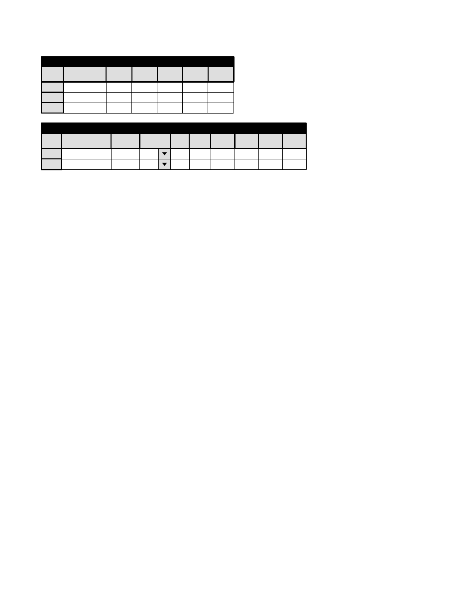
Figure 5−36. Switcher Input and Output
tables for application shown on page 5−49.
1
Name
VT01
RIGHT
VIDEO
2
VT02
3
SAFE
LEFT
TC
001
002
002
Switcher Input − MAINROUT
001
001
001
001
DATA
064
002
002
1
Switcher Output − MAINROUT
Name
VT01
Security
S−T
−
VIDEO
001
LEFT
001
RIGHT
001
TC
001
2
VT02
−
002
002
002
002
Pass
DATA
001
002
Word
002
Logical Input
Logical Output
CP Input and Output Sets and Control Panel Operation
The input and output names in the previous tables must be assigned to Category/Entry selections using a CP Input Set (page
5−58) and CP Output Set (page 5−76). For example, if a CP−3000−type panel is to be used, the “C” (for “controller”) category
button could be used to select the controller (output) and the VCR category button could be used to select the VCRs .