Model 200 production switchers, Gvg 200 (p. 5−130), P. 3−3 – Grass Valley VM 3000 System Controllers v.7.4 User Manual
Page 340
Configurator
MPK Devices
5−130
VM 3000 Installation and Operating Manual
MODEL 200 PRODUCTION SWITCHERS
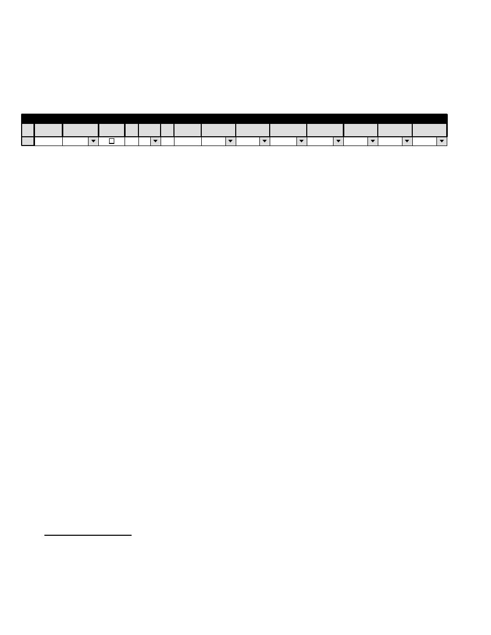
Hardware installation was discussed on page 2−88; serial port configuration was discussed on page 5−27. Figure 5−105 shows
an example table for the system on page 2−88.
GVG
GVG200
SI3
2
06
GVG−INP
GVG−OUT
KXYZ−LEV
1
MPK Devices
MPK
Expansion
Pass
Board
Port
Address
Input Sets
Output Sets
Level Set
Overide Set
Sequence Set
Devices
word
In Panel
Out Panel
Figure 5−105. Entry for system shown on page 2−88.
Device
Type
The “Address” shown on this table may appear to be the address of the production switcher, but is in fact the address of the
VM/SI 3000 on the Model 200 Peripheral bus. This address must be a number between 000000000 and 00000023.
Note: Due to a Jupiter software limitation, connecting Peripheral devices in addition to the single VM/SI is not
recommended. MPK Device Address “06” has been tested and is known to work when Model 200 Peripheral
devices “01” and “02” are both enabled (even though only one device is actually present).
†
The CP Input (page 5−58) and Output (page 5−76) sets must be created specifically for use by “E−MEM” devices.
Configuration − Production Switcher
The Peripheral bus and the VM/SI 3000 must be enabled from the production switcher:
“From the [production] switcher operator’s viewpoint, the PERIPH ENABLE pushbutton on the Model 200 panel
must be ON to enable communication over the Peripheral Bus. Specific peripherals are enabled or disabled for
participation in the E−MEM Learn [or Recall] via the MISC menu in the STREAMLINE control panel. This menu
contains the selections for turning any or all of the 24 possible peripherals ON or OFF. After the operator has made
these selections, the [production] switcher’s internal software generates the correct peripheral Learn [or Recall]
command data and transmits it over the Peripheral Bus whenever the operator sets up an E−MEM Learn [or Recall]
of the USER PGM level and presses an E−MEM register pushbutton.”
††
Refer to the Model 200 production switcher manual for additional installation and operating instructions.
†
For a technical discussion of this limitation, see Field Engineering Bulletin 071827506.
††
Model 200 Peripheral Interface II Protocol and Dialect (Grass Valley Group Manual Number TP0424−00, June 1988)
, p.
3−3.