Switcher description, Switcher input, Switcher output – Grass Valley VM 3000 System Controllers v.7.4 User Manual
Page 241: Is first connected to a distribution switcher
Configurator
Switcher Description Table
5−31
VM 3000 Installation and Operating Manual
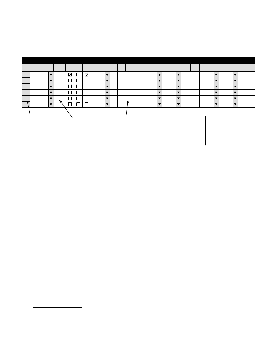
Switcher Description
Logical level
number
Logical level
name
Physical level
number
1
Switcher Description
MAINROUT
VM1
64
64
1
Binary
None
2
MAINROUT
VM1
64
64
2
Binary
Left
3
MAINROUT
VM1
64
64
6
Binary
Right
4
MAINROUT
VM1
64
64
3
Binary
None
VIDEO
LEFT
RIGHT
TC
5
MAINROUT
VM1
65
65
16
DM400B
Enforce
DATA
6
Switcher
VI
RV
Board
#In #Out PLvL
Follow Level
Driver
3 LI
3 LO
Option
Audio
Level
DM 400
MC
Off Time
Figure 5−21. Switcher Description table (example).
Password
Switcher Description
Switcher Input
Control Panel Sets
Level set
Machines
TCS−1 Device Codes
Status Display Header
Tally
Exclusion
This table must be used when the VM 3000 or CM 4000
†
is first connected to a distribution switcher.
§
Each logical level number of the switcher is given a user−specified name up to eight characters in length, and the system is
provided with detailed information about each level.
†
CM 4000 installation is described in the CM 4000 Installation and Operating Manual.
§