Hardware components, Routing switcher control panel, Production switcher – Grass Valley VM 3000 System Controllers v.7.4 User Manual
Page 738
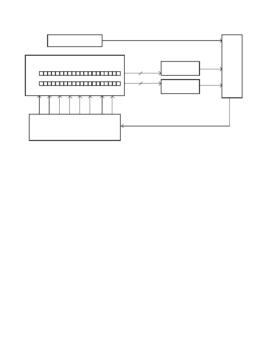
Input Source Assignment
VM 3000 Installation and Operating Manual
R−2
Production Switcher
PST
PGM
Inputs
Outputs
Video Routing Switcher
MI 3040 Lock
PST Tally
PGM Tally
(40 Max)
VM/SI
Xpoint Bus
CP 38xx
MPK
MPK
MPK
3000
MI 3040 Select
Must connect to the same control board
w
w
w
w
Figure R−2.
1.
The operator selects the desired Preset button on the production switcher. This energizes the appropriate PST Tally
line for that input; this condition is detected by a dedicated MI 3040 General Purpose Parallel Interface. Software
within the VM/SI 3000 can now determine which router output is associated with the Preset button just pressed.
2.
Control of the router output is automatically given to a CP 38xx series panel, which the operator now uses to select
the desired input; for example, Camera 1. Camera 1 is now assigned to the Preset button selected on the production
switcher.
3.
When the signal on the Preset bus is taken to air, a similar process is used to detect this event. A second MI 3040 uses
the Program Tally lines to determine which signal is on−air; the VM/SI 3000 uses this information to lock the router
output involved. In this example, if Camera 1 was now on−air, the CP 38xx panel would not be able to switch to
another source until Camera 1 was taken off−air.
HARDWARE COMPONENTS
Routing switcher control panel
This can be a CP 3808, CP 3824, CP 3832, CP 3864, or CP 3830 control panel. These are all single output panels.
Note: The CP 3800A and CP 3830P (CP 3830 operated in Preview mode) cannot be used in this application.
The control panel operation has not been changed due to the implementation of these new features. The system also allows
each new device to be associated with a different CP−38xx panel if desired.