Appendix j, Cp 3000 control panel basic operation, Input to output switching – Grass Valley VM 3000 System Controllers v.7.4 User Manual
Page 703: See appendix j, Vtr1 vt1l vt1r vt1t blk bars tone slnc, Input to output switching the cp 3000, Ab c d, F4 f3 f2 f1

J−1
VM 3000 Installation and Operating Manual
Appendix J
CP 3000 Control Panel Basic Operation
INPUT TO OUTPUT SWITCHING
The CP 3000
†
is a full−matrix control panel, designed to route any source to any destination. (However, access to certain
destinations may be limited by the system administrator.)
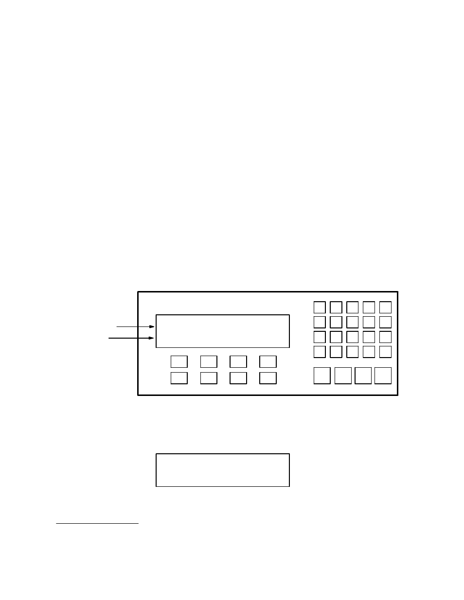
Looking at Figure J−1, we’ll break the panel up into a couple of groups. The first area is the display window. The top row
in the display window shows you the status of each level in the router for a particular destination.
Using the CLEAR key, the bottom row can be toggled between the first page of input override selections (as shown in Figure
J−1) and the name of the current output (Figure J−2).
To the right of the control panel is a keypad; this includes all the numbered and lettered buttons. Directly beneath the keypad
is a row of buttons that have designated functions.
Figure J−1. CP 3000 Switcher control panel with example Status/Override display.
Status for 4 levels
Overrides
VTR
1
CG
2
NET
3
SAT
EJ
VCR
4
CAM
5
REM
6
FILM
7
PTCH
8
STU
9
FS
AUX
TEST
0
MISC
SS
A
B
C
D
TAKE
CHOP
LOCK
PROT
F4
F3
F2
F1
MORE
CLR
MENU
LEV
VTR1 VT1L VT1R VT1T
BLK BARS TONE SLNC
Figure J−2. Press CLEAR to toggle to Status/Output display
VTR1 VT1L VT1R VT1T
CURRENT OUT = VTR1
†
