See figure 2−42 for a description of this cable, See figure 2−43 – Grass Valley VM 3000 System Controllers v.7.4 User Manual
Page 105
Hardware Installation
2−33
VM 3000 Installation and Operating Manual
1
2
3
7
8
1
2
8
P1
DB9P
(male)
Shield (drain)
Green
Black
White
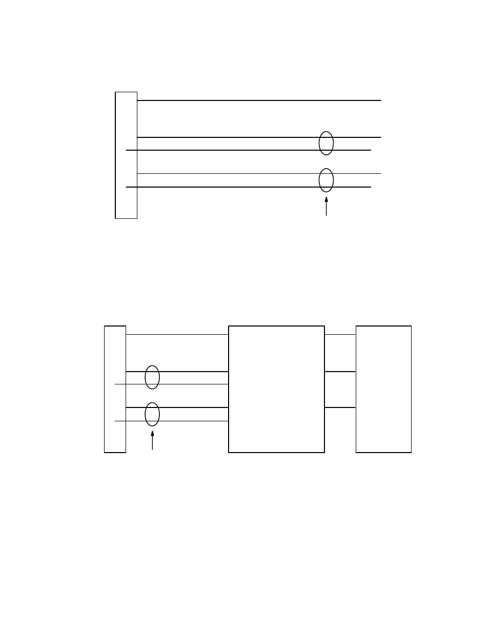
Figure 2−42. Cable for connecting VM 3000 to Vistek RS−422 port.
3
7
Red
Frame ground
Receive A (−)
Transmit A (−)
Receive B (+)
Transmit B (+)
Transmit B (+)
Transmit A (−)
Receive B (+)
Receive A (−)
Frame ground
Twisted pairs
VM 3000 control board
Vistek RS−422 Port
1
2
P1
DB9P
(male)
Figure 2−43. Cables for connecting VM 3000 to Vistek RS−232 port.
3
Vistek RS−232 Port
Frame ground
Transmit
Receive
Frame ground
Receive
Transmit
1
2
3
7
8
P1
DB9P
(male)
Shield (drain)
Green
Black
White
Red
Frame ground
Receive A (−)
Transmit A (−)
Receive B (+)
Transmit B (+)
Transmit B (+)
Transmit A (−)
Receive B (+)
Receive A (−)
Frame ground
Twisted pairs
VM 3000 control board
RS−422/232
converter