User defined addresses, Printer, Figure 2−53 – Grass Valley VM 3000 System Controllers v.7.4 User Manual
Page 116
Hardware Installation
2−44
VM 3000 Installation and Operating Manual
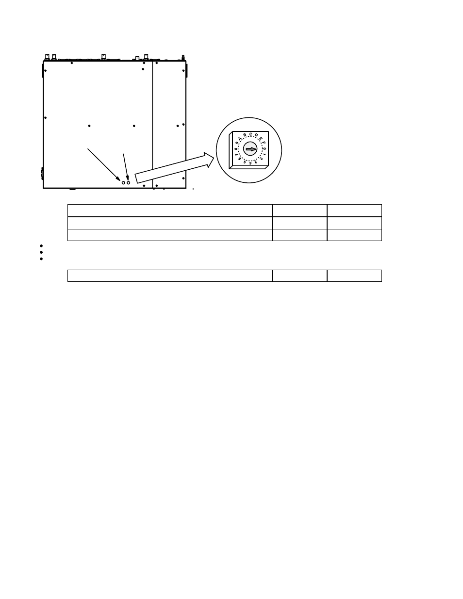
S2 (LSB)
S3 (MSB)
Figure 2−53. Access holes for VM/SI 3000 “Device”
rotary switches.
Switch S3
Switch S2
Conventional LAN operation
0
0
Beginning of user−defined addresses
0
1
End of user−defined addresses
F
E
Figure 2−54. Rotary switch settings..
For conventional LAN installation S2 and S3 are set at “00.”
This causes the unit to use the address stored in the hardware address PROM, i.e., the address shown on the rear panel. This
address must be entered on the Network Description table (page 5−22).
USER DEFINED ADDRESSES
If for some reason the VM 3000 (or an SI 3000) needs to be removed from a LAN, and replaced by another VM/SI 3000, this
would normally require the address of the new unit to be entered on the Network Description table and the modified configura-
tion set to be activated. However, it is possible to avoid changing the Network Description table and instead use S2 and S3
to set the VM/SI 3000 to the address 0080CEDEADxy, where x is set with S3 and y is set with S2; the address “0080CE-
DEADxy” is entered permanently on the Network Description table. For example: address “0080CEDEAD01” could be en-
tered on the table; thereafter each VM/SI 3000 connected to the LAN could be set with S3 at “0” and S2 at “1.”
This technique can be used in redundant installations where a third VM/SI is maintained as a replacement for a failed redun-
dant unit. For more information, see Appendix K.
PRINTER
A printer can be connected to the LPT1 port and used to print the contents of an entire Configuration Set in a 132−column
format; it can also be used to print the contents of individual tables (page 5−16).