Ab c d, F4 f3 f2 f1, Figure j−8 – Grass Valley VM 3000 System Controllers v.7.4 User Manual
Page 706: Figure j−9
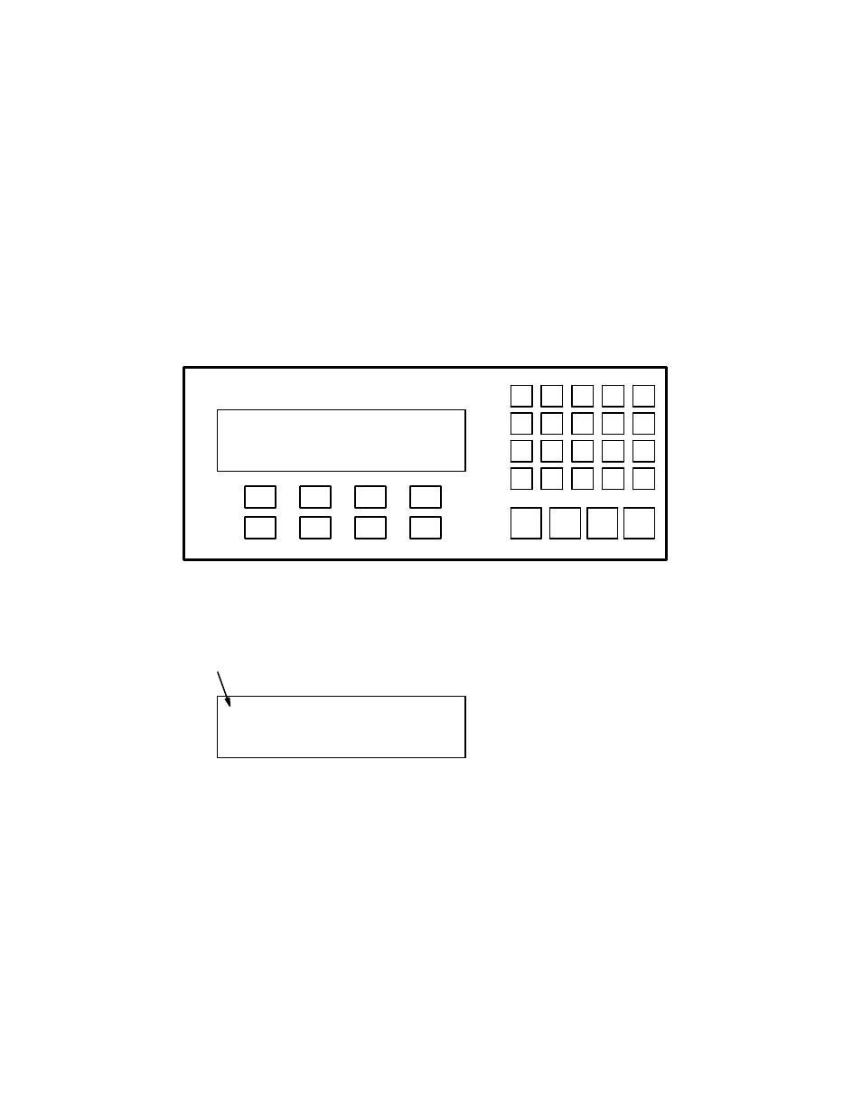
CP 3000 Basic Operation
J−4
VM 3000 Installation and Operating Manual
Let’s try a simple switch. For example, let’s put VTR1 into VTR2. The first thing you would do when you walk up to a panel
is find out what destination the panel is controlling. To do this, you would look for the “CURRENT OUT = ” message; if you
don’t see it, press CLR until you do.
If you are happy with the output being controlled, we can now change the source feeding our machine. Going to the keypad,
press VTR, 1, and then the TAKE button. You have now called up VTR1 into your machine. You will notice the top row in
the display window will show VTR1 for the video level and both audio levels.
Another way of calling up a source is to use the override buttons. The bottom row of the display window in the home menu
describes which override each function button represents. By pressing the F2 button and then the TAKE button, you will have
sent BARS into VTR2.
VTR
1
CG
2
NET
3
SAT
EJ
VCR
4
CAM
5
REM
6
FILM
7
PTCH
8
STU
9
FS
AUX
TEST
0
MISC
SS
A
B
C
D
TAKE
CHOP
LOCK
PROT
F4
F3
F2
F1
MORE
CLR
MENU
LEV
Figure J−8.
VTR1 VT1L VT1R VT1T
LOCK PRESS TAKE
LVTR1 VT1L VT1R VT1T
BLK BARS VTR1 VTR2
Lock symbol
Figure J−9.