Grass Valley VM 3000 System Controllers v.7.4 User Manual
Page 679
3−Stage Switching
H−3
VM 3000 Installation and Operating Manual
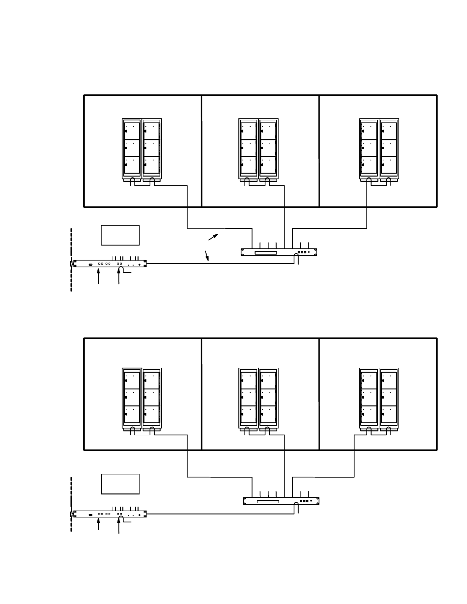
Figure H−2. Two logical levels of a Venus 512 x 512 three−stage switcher.
VM 3000
“VM1”
LAN
Crosspoint bus
CB−3000
Sync
Time
code
Input stage
Actual and configuration size 32 16 x 32 (512 inputs)
Intermediate stage
Actual size 32 32 x 32
Output stage
Actual size 32 32 x 16 (512 outputs)
Configuration size 32 32 x 32 (1024 outputs)
Physical level 3.
Physical output numbers 0 − 1023
“VIDEO”
Physical level 2.
Physical output numbers: 0 − 1023
For additional details concerning VM
3000/CB−3000 connections, see page 2−3.
Physical level 1.
Physical output numbers: 0 − 1023
†
CB−3000
“LEFT”
VM 3000
“VM2”
Sync
Time
code
†
Actual number of outputs is 512 (only one out-
put board is installed in each sub−switcher).
Physical level 3.
Physical output numbers 0 − 1023
Physical level 2.
Physical output numbers: 0 − 1023
Physical level 1.
Physical output numbers: 0 − 1023
†