Grass Valley VM 3000 System Controllers v.7.4 User Manual
Page 282
Configurator
CP Input Set
5−72
VM 3000 Installation and Operating Manual
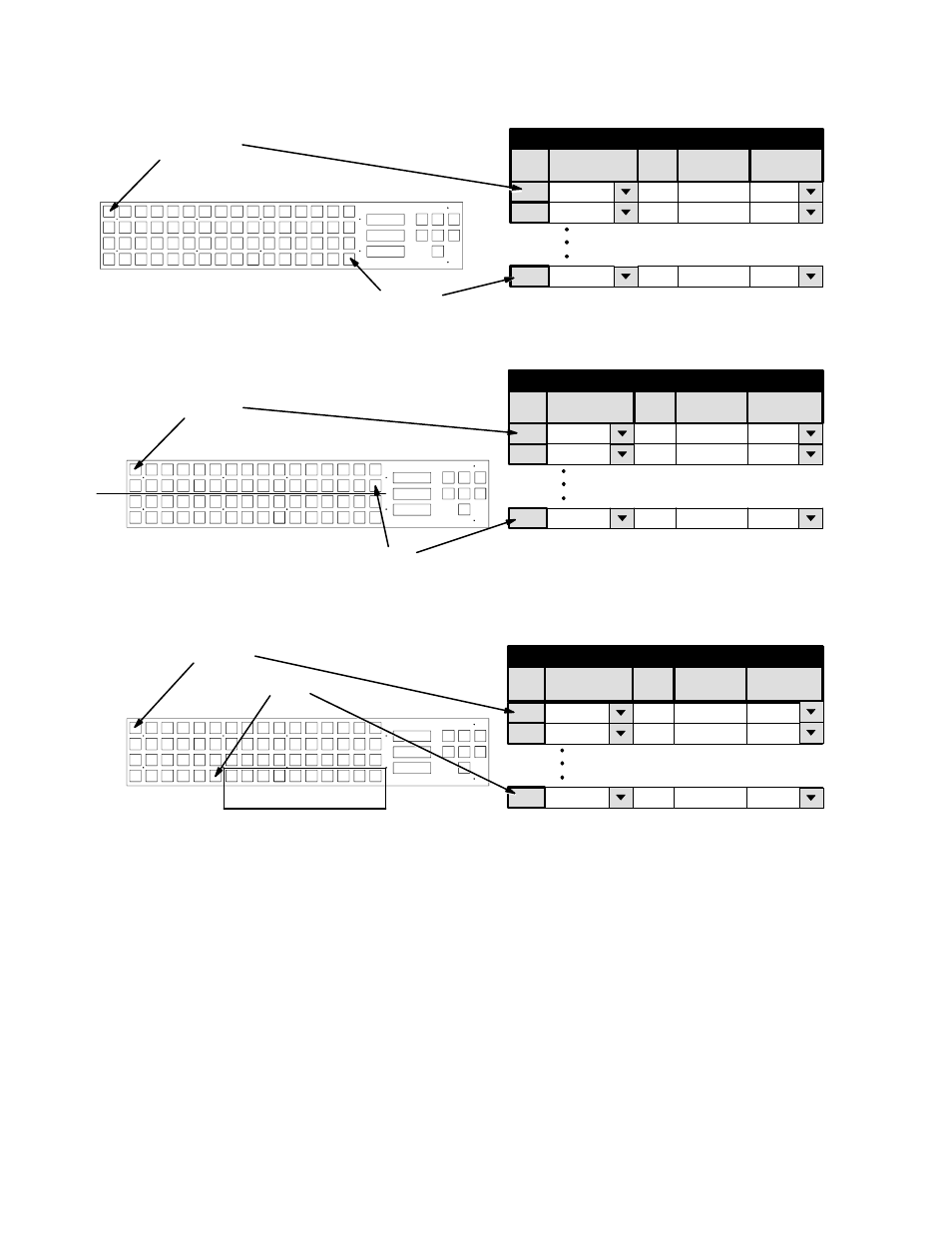
Input button 1
Input button 64
Figure 5−54. Entries for CP 3864 operated as single−
bus panel.
1
CP Input Set − 3832−IN
default
2
default
1
2
Category
Entry
CAM1
CAM2
Input
64
default
64
VTR12
CAM1
CAM2
Mnemonic
VTR12
†
†
†
Logical
Input button 1
Input button 32
IN
OUT
Figure 5−55. Entries for CP 3864 configured as 32 x 32
“balanced split” panel. Balanced number of input/output
buttons is determined by output assignments made on the
CP Output Set. For details, see page 5−92.
Category
1
CP Input Set − 3832−IN
default
2
default
1
2
Entry
CAM1
CAM2
Input
32
default
32
VTR12
CAM1
CAM2
Mnemonic
VTR12
†
†
†
Logical
Input button 1
Input button 54
IN
OUT
Figure 5−56. Entries for CP 3864 configured as 54 x 10
“unbalanced split” panel. Total number of input buttons
vs. total number of output buttons is determined by num-
ber of output assignments made on the CP Output Set.
For details, see page 5−92.
Category
1
CP Input Set − 3832−IN
default
2
default
1
2
Entry
CAM1
CAM2
Input
54
default
54
VTR12
CAM1
CAM2
Mnemonic
VTR12
†
†
†
Logical