Y line table (dm 400/400a) – Grass Valley VM 3000 System Controllers v.7.4 User Manual
Page 419
Configurator
Y Line
5−209
VM 3000 Installation and Operating Manual
Y Line Table (DM 400/400A)
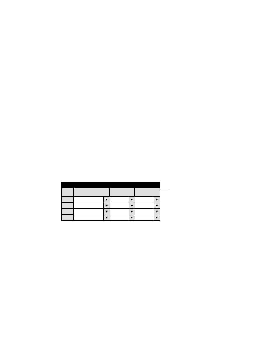
Figure 5−181. Y Line table (example).
1
Y Line Table
Level
REV (DATA)
2
FOR (DATA)
Input
VR2−S
Output
VR2−M
VR2−M
VR2−S
3
REV (DATA)
4
FOR (DATA)
VR1−S
VR1−M
VR1−M
VR1−S
Logical
Logical
Switcher Description
Control Panel Sets
Machines
TCS−1 Device Codes
Status Display Header
Tally
Path Finding
Exclusion
The Y Line table is used only with Venus data routers equipped with DM 400 or DM 400A Data Matrix boards in applications
where a VTR can be used as a controller (master) on some occasions and as a tributary (slave) on others.
Note: This table is not used with newer model Venus systems equipped with the DM 400B Data Matrix boards;
these boards have software−configurable rear−panel pinout functions and do not require Y−line cables.
Configuration of this table is described at the conclusion of Appendix L, “Special configuration requirements: Venus DM
400/400A data matrix switching.”