Software configuration – Grass Valley VM 3000 System Controllers v.7.4 User Manual
Page 202

Hardware Installation
2−130
VM 3000 Installation and Operating Manual
CONNECTION TO SYSTEMS WITH SATURN MASTER CONTROL SWITCHER
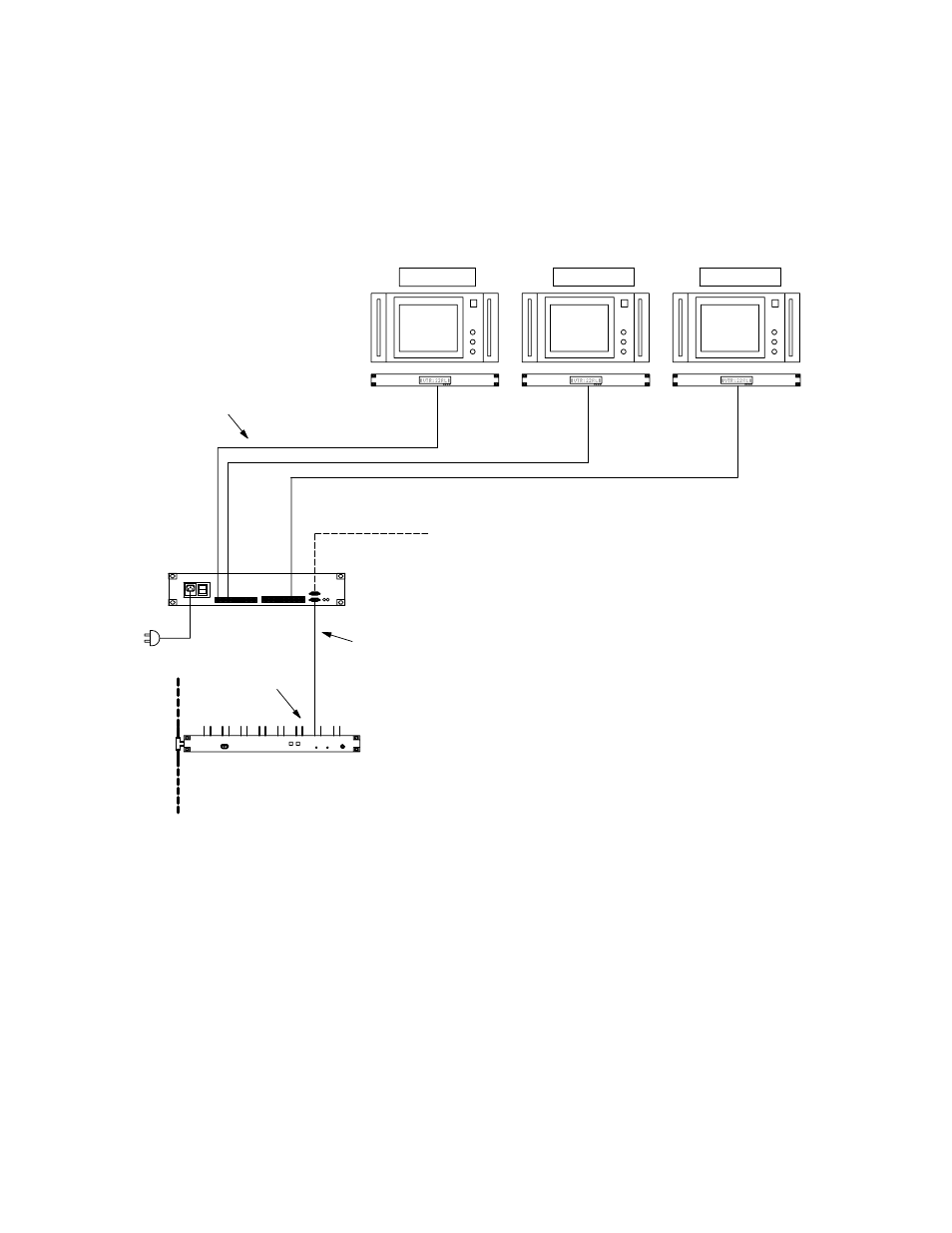
A master control room application is shown in Figure 2−144. No additional connections to the master control switcher itself
is required, since all status data is transmitted on the LAN (page 2−112).
Figure 2−144. Example of Saturn master control room installation.
PRESET
PROGRAM
AIR
Serial data cable (see page 2−109)
SlimLine UMD Controller
AC
power
MPK bus
MPK bus loop to additional
SlimLine Controllers
Cat 5 cable
(see Note 2 on page 2−128)
Serial ports
VM/SI 3000
LAN
Software configuration
Two methods are available for configuring UMDs with Saturn systems:
S “Saturn control” − in most cases this will be the preferred method because 1) it involves fewer tables, 2) it will
provide status of inputs connected to the Saturn Internal Matrix Option, and 3) it is designed to integrate with
the “Monitor Follow” function of Saturn. For more information, refer to the “Saturn UMD” discussion in the
Saturn Installation and Operating Manual.
S “Jupiter control” − the original method for configuring master control UMDs, largely replaced by the “Saturn
control” method—especially because Jupiter control cannot be used to status inputs connected to the Saturn
Internal Matrix Option. However, the Jupiter control method may still be useful in special circumstances, as
described below.
