Connection to serial and esbus vtrs, See figure 2−106 – Grass Valley VM 3000 System Controllers v.7.4 User Manual
Page 162
Hardware Installation
2−90
VM 3000 Installation and Operating Manual
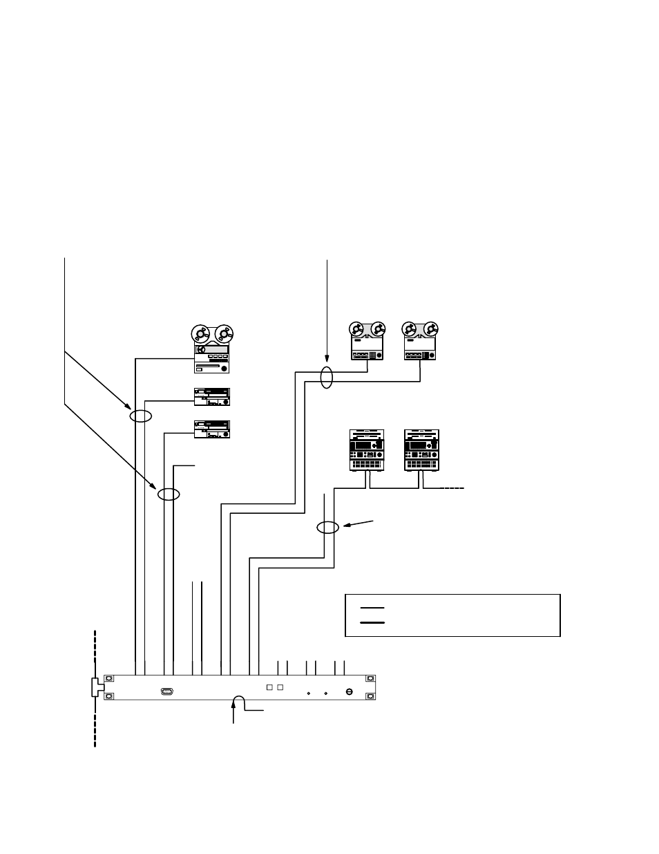
CONNECTION TO SERIAL AND ESBUS VTRS
VTRs are connected to the LAN through a VM/SI 3000 system controller board. The protocol for these ports must be set in
pairs. (The protocol is set at the file server, as described later in this manual.) In the example shown in Figure 2−106, ports
1 through 4 are configured for Sony serial machines, ports 7 and 8 for Ampex serial VTRs, and 9 and 10 for ESbus devices
(such as Philips DCR Series VTRs). Notice that because the port protocol is set in pairs port 4 must be reserved for use with
a Sony serial VTR.
Serial (Sony) bus
1
SI 3000
VPR−3 VPR−80
VPR−6 VPR−300 series
Serial bus (ESbus)
3
Philips DCR 100/300/500
Figure 2−106. Connection to late−model serial and ESbus VTRs.
Serial data cable (see page 2−109)
BVH−2000 BVW−10
BVH−2500 BVW−40
BVU−800
BCB−35/60/65/70/75
DCR−10/18/20/28/34/35
PCB−2600/2650/2800
Serial (Ampex) bus
2
1
2
3
Reserved for
Sony serial VTR
4
5
6
7
8
9
10
2
See Ampex Installation Notes, page 2−91.
3
See ESbus Installation Notes, page 2−92.
Sync ref.
See pg.
1
See Sony Installa-
tion Notes, page