Cp 3832 / 3864 control panels, Passwords, Vtr−041 – Grass Valley VM 3000 System Controllers v.7.4 User Manual
Page 520: Vtr−041 monitor5
Control Panel Operation
CP 3832 / 3864
6−100
VN 3000 Installation and Operating Manual
CP 3832 / 3864 Control Panels
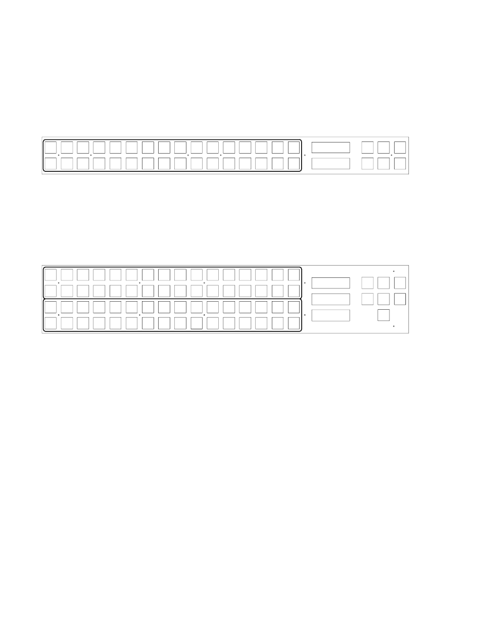
The CP 3832 is a button−per−source control control panel configurable for single bus* (32 X 1) or “split” operation. In split
configurations some of the buttons control inputs and some control outputs. The panel includes buttons for TAKE, LOCK,*
and PROTECT.* For installation and configuration instructions, please see page 2−63.
VTR1
VTR2
VTR3
VTR4
VTR5
VTR6
VTR7
VTR8
CAM1
CAM2
CAM3
CAM4
CAM5
CAM6
CAM7
CAM8
BLACK
BARS
TONE
CG−1
SILE
NCE
CG−2
CG−3
CG−4
EBS1
EBS2
TEST1
TEST2
FDL1
FDL2
FDL3
FDL4
Level
Menu
Clear
Prot/
Lock
Pre−
set
Take
CURRENT
PRESET
VTR−041
VTR−041
Figure 6−128. CP-3832.
The similar CP 3864 is configurable for single bus (64 X 1) or “split” operation. The panel has all of the CP 3832 control
buttons, plus a CHOP button. A “Destination” window is also provided. For installation and configuration instructions, please
see page 2−65.
VTR1
VTR2
VTR3
VTR4
VTR5
VTR6
VTR7
VTR8
CAM1
CAM2
CAM3
CAM4
CAM5
CAM6
CAM7
CAM8
BLACK
BARS
TONE
CG−1
SILE
NCE
CG−2
CG−3
CG−4
EBS1
EBS2
TEST1
TEST2
FDL1
FDL2
FDL3
FDL4
MON1
MON2
MON3
MON4
MON8
MON6
MON6
MON5
STU1
STU2
STU3
STU4
EDIT1
EDIT2
EDIT3
EDIT4
PST
PGM
AIR
KEY1
KEY2
BACK
UP
BY
PASS
XMIT
VTR1
VTR2
VTR3
VTR4
VTR5
VTR6
VTR7
VTR8
Level
Menu
Clear
Chop
Lock/
Prot
Pre−
set
Take
CURRENT
PRESET
DESTINATION
VTR−041
VTR−041
MONITOR5
Figure 6−129. CP-3864.
All push buttons are capable of green, amber, and red back lighting. On the left side of the panel, green indicates inputs and
amber indicates outputs. On the right side, green is generally used to show a selected function and red to indicate an operation-
al mode in progress.
In some applications, the panels will be grouped with additional CP 3832s or CP 3864s to provide control of up to a 128 X
128 router; or, operated in connection with an adjacent CP 3810 Expansion Panel (see page 6−126).
PASSWORDS
Note: For a general description of the Jupiter password system, please see page 5−17.
If entry of a password (“PASS =00”) is requested, the output about to be affected has a password level higher than that of the
panel. Enter the appropriate password, using the first 10 buttons of the CP 3832/64 to enter digits from 0 to 9 (as shown on
page 6−143).
After entry of a higher−level six−digit password, the command can be completed by pressing TAKE; however, the panel will
then revert to its previous password level.