Appendix a, Vm 3000 vga status display, Hardware installation – Grass Valley VM 3000 System Controllers v.7.4 User Manual
Page 647: Refer to appendix a for installation instructions, See appendix a, Figure a−3. vga status display installation
A−1
VM 3000 Installation and Operating Manual
Appendix A
VM 3000 VGA Status Display
HARDWARE INSTALLATION
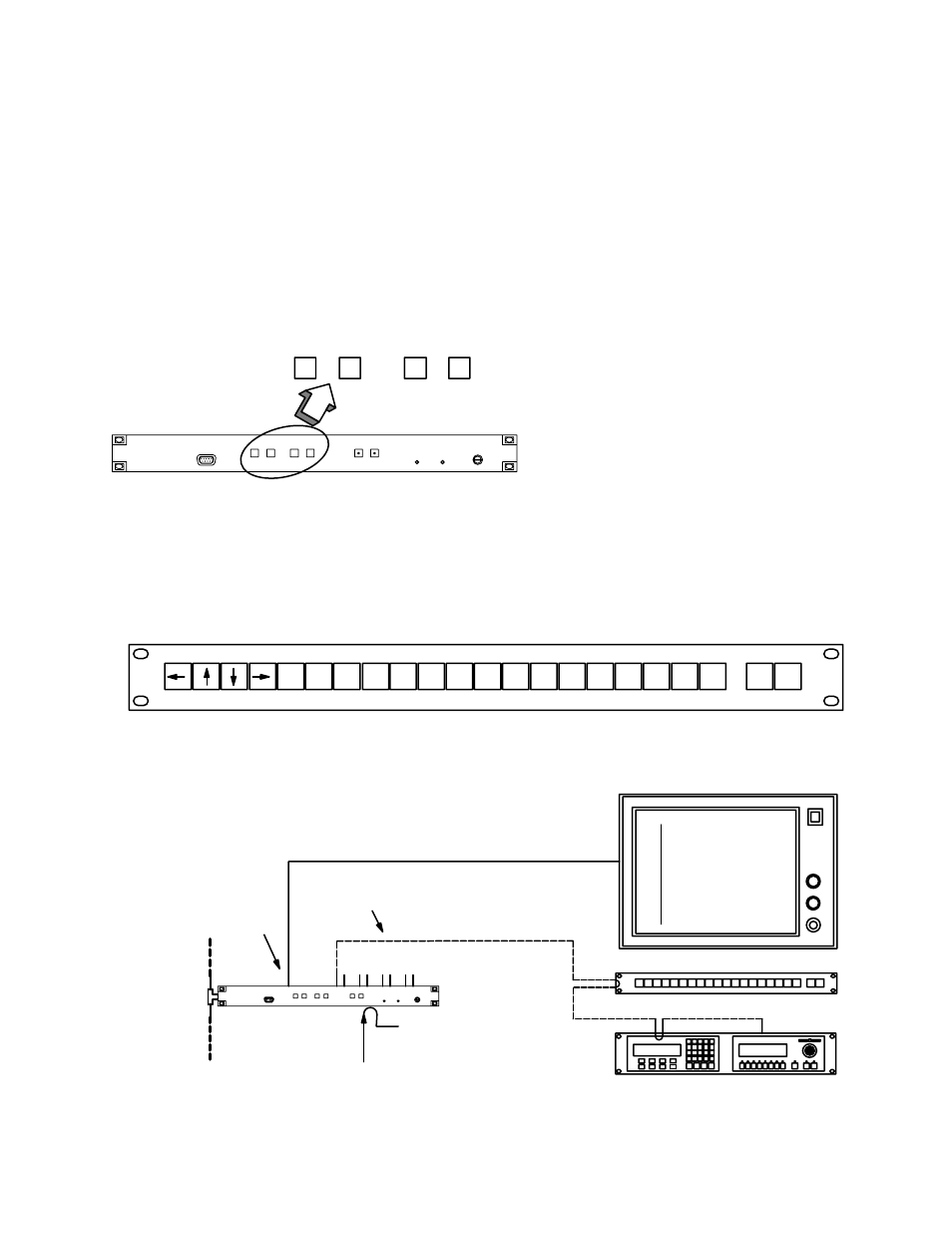
The VM 3000 provides a VGA output for system status display. Basic controls for this display are located on the front panel
(Figure A−1).
UP
DOWN
NEXT
SELECT
Figure A−1. VGA controls on VM 3000
The VM 3000 VGA Status Display can optionally be operated with the CP 3020, a 1 3/4−inch rack mount panel configured
as a device type “VC 3020.” (Figure A−2.) To use the VGA display to best advantage, it should also be connected to a dedi-
cated CP 3000 Switcher Control Panel (configured as a “VCP 3000”) and an MC 3000 Machine Control Panel (configured
as a “VMC 3000”). Grass Valley recommends that all panels be mounted immediately beneath the VGA monitor. These panels
can be on different MPK buses, but they must all be connected to the VM 3000 being used to drive the VGA display. See Figure
A−3.
Figure A−2. CP 3020 with suggested VC 3020 labelling.
NEXT
CURSOR
MODE
CHNG
MODE
0
9
1
2
3
4
5
6
7
8
Figure A−3. VGA Status Display installation.
VGA cable
25 feet (8 m) max.
Sync ref. See
Video Out
(VGA)
VM 3000
MPK bus to
optional controls
CP 3000 Switcher
Control Panel
CP−3020 (VC 3020)
MC 3000 Machine
Control Panel
LAN
See pg
Serial data cable (see
page 2−109)
Philips WXYZ TELEVISION ROUTER/VTR STATUS PAGE: 00
May 10, 1999 SWITCHER STATUS 12:34:56
−−−−−−−−−−−−−−−−−−−−−−−−−−−−−−−−−−−−−−−−−−−−−−−−−−−−−−−−−−−−−−−−−−−−−−−−−−−−−−−−
OUTPUT VIDEO LEFT RIGHT TC
−−−−−−−−−−−−−−−−−−−−−−−−−−−−−−−−−−−−−−−−−−−−−−−−−−−−−−−−−−−−−−−−−−−−−−−−−−−−−−−−
PrdA VT01 VT01 VT01 VT01
PrdB VC01 VC01 VC01
PrdC Cam1 Cam1 Cam1
PrdC Cam1 Cam1 Cam1
PrdC Cam1 Cam1 Cam1
PrdC Cam1 Cam1 Cam1
PrdC Cam1 Cam1 Cam1
PrdC Cam1 Cam1 Cam1
PrdC Cam1 Cam1 Cam1
PrdC Cam1 Cam1 Cam1
PrdC Cam1 Cam1 Cam1
PrdC Cam1 Cam1 Cam1
PrdC Cam1 Cam1 Cam1
PrdC Cam1 Cam1 Cam1
PrdC Cam1 Cam1 Cam1
PrdC Cam1 Cam1 Cam1
PrdC Cam1 Cam1 Cam1
PrdC Cam1 Cam1 Cam1
PrdC Cam1 Cam1 Cam1
PrdC Cam1 Cam1 Cam1
PrdC Cam1 Cam1 Cam1
PrdC Cam1 Cam1 Cam1
PrdC Cam1 Cam1 Cam1
PrdC Cam1 Cam1 Cam1
PrdC Cam1 Cam1 Cam1
PrdC Cam1 Cam1 Cam1
PrdC Cam1 Cam1 Cam1