Mi 3040 (“mc 3040”) installation – Grass Valley VM 3000 System Controllers v.7.4 User Manual
Page 176
Hardware Installation
2−104
VM 3000 Installation and Operating Manual
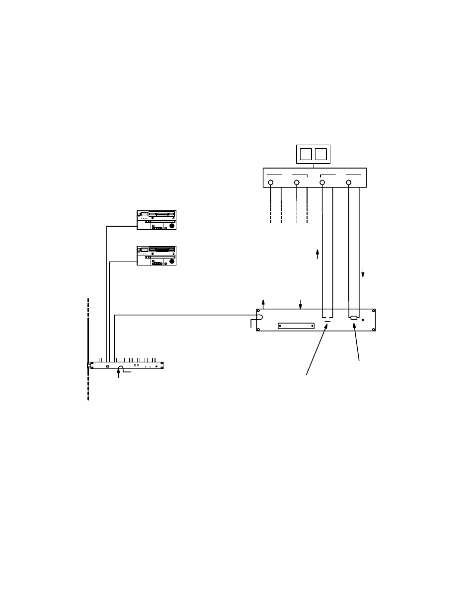
CONNECTION TO NON−JUPITER MACHINE CONTROL PANEL OR COMPUTER
MI 3040 (“MC 3040”) Installation
Figure 2−118. External machine control using MI 3040 (“MC 3040”).
LAN cable
(see page
SI 3000
“SI1”
MPK bus
MI 3040 (“MC 3040”)
General Purpose/Tally Interface
Serial data cable (see page 2−109)
+5 V, 1 A utility
connection
Ground utility
connection
Machine control panel
or computer
(customer supplied)
1 of 40 relays.
See Fig. 2−137
on page 2−124.
1 of 40 opto−
isolators. See
Fig. 2−138 on
page 2−124.
Stop
Command
Status
Sync ref.
See pg.
Play
Stop
Play
Stop
With the MI 3040 General Purpose / Tally Interface, a customer−supplied external machine control panel or device can use
the Jupiter system to transmit commands to, and receive status from, a VTR or similar machine. In this application, the MI
3040 is configured in software as an “MC 3040.” It will be referred to as such for the balance of this discussion. The MC
3040 and MI 3040 hardware is identical.
Commands such as “start“ and “stop” are sent from the external machine control device to the opto−coupler inputs; these
respond to a differential voltage between the two input pins. Status information is returned from the machine to the MC 3040
relays, which are suitable for low−voltage (<100 V), low−current (<300 milliamps) applications. Each relay may be config-
ured by slide switch for normally−open or normally−closed operation. For hardware details, please see page 2−123.