Motorola ColdFire MCF5281 User Manual
Page 742
Revision History
B-6
Freescale Semiconductor
Table 8-3/8-5
Add the following note to the BDE bit description: “The SPV bit in the CPU’s RAMBAR must also be set
to allow dual port access to the SRAM. For more information, see Section 5.3.1, ‘SRAM Base Address
Register (RAMBAR).’”
Figure 9-1/9-3
Remove
÷
2 from CLKGEN block.
10.3.6/10-11
Add this text to the end of the first paragraph: “If a specific interrupt request is completely unused, the
ICRnx value can remain in its reset (and disabled) state.”
10.5/10-17
Added the following note: “The wakeup mask level taken from LPICR[6:4] is adjusted by hardware to allow
a level 7 IRQ to generate a wakeup. That is, the wakeup mask value used by the interrupt controller must
be in the range of 0–6.”
Figure 12-4/12-8
Changed CSCRn to reflect that AA is set at reset.
13.5/13-15
Removed final paragraph. The paragraph incorrectly states that the MCF5282 does not have a bus
monitor.
Table 14-3/14-11
Changed pull-up indications in the ‘Internal Pull-Up’ column.
Table 17-13/17-26
Change encodings for bits 31–9 to:
0 The corresponding interrupt source is masked.
1The corresponding interrupt source is not masked.
Chapter 19
Change PIT1–PIT4 to PIT0–PIT3 throughout chapter. When a timer is referenced individually, PIT1
should be PIT0, PIT2 should be PIT1, PIT3 should be PIT2, and PIT4 should be PIT3. Other chapters in
the user’s manual use the correct nomenclature: PIT0–PIT3.
19.6.3/19-7
Change timeout period equation to the equation below.
Figure 23-11
Change UISR bits 5–3 to reserved bits
24.6.1/24-11
Change ‘I2CR = 0xA’ to ‘I2CR = 0xA0.’
27.2.1/27-2
Changed ‘When interfacing to 16-bit ports, the port C and D pins and PJ[5:4] (BS[1:0]) can be configured
as general-purpose input/output (I/O)’
32.2/32-7
Added additional device number order information to
for MCF5280 and MCF5281 at 66- and
80-MHz, and MCF5282 at 80 MHz.
Chapter 33
Delete references to ‘T
A
= T
L
to T
H
’.
Table 33-1/33-1
Replace V
in
row with the row below, in which the maximum value has been changed to 6.0 V.
Table 33-6/33-8
Replace I
DDA
row with the row below, in which the maximum value in normal operation has been changed
to 5.0 mA.
Figure 33-5/33-16
Replaced figure, “SDRAM Read Cycle”
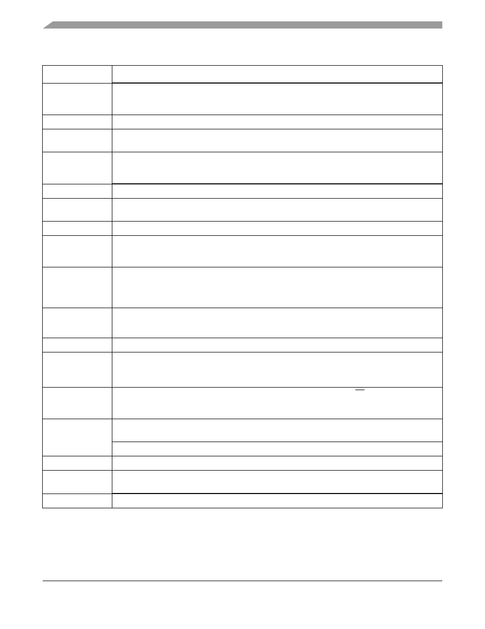
Table B-3. Rev. 1 to Rev. 2 Changes (continued)
Location
Description
Timeout period
PRE[3:0]
(PM[15:0]
1)
+
2
Ч
Ч
system clock
-----------------------------------------------------------------------------
=
MCF5282 and MCF5216 ColdFire Microcontroller User’s Manual, Rev. 3