2 register descriptions, 1 synthesizer control register (syncr), 2 register descriptions -6 – Motorola ColdFire MCF5281 User Manual
Page 176: 1 synthesizer control register (syncr) -6
Clock Module
9-6
Freescale Semiconductor
9.6.2
Register Descriptions
This subsection provides a description of the clock module registers.
9.6.2.1
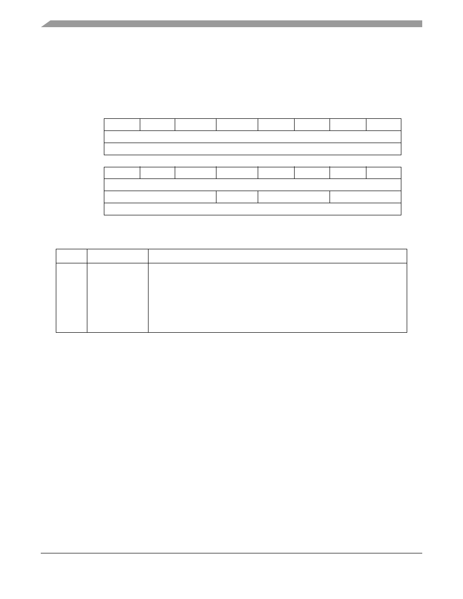
Synthesizer Control Register (SYNCR)
15
14
13
12
11
10
9
8
Field
LOLRE
MFD2
MFD1
MFD0
LOCRE
RFD2
RFD1
RFD0
Reset
0010_0001
R/W
R/W
7
6
5
4
3
2
1
0
Field
LOCEN
DISCLK
FWKUP
—
STPMD1
STPMD0
—
—
Reset
0000_0000
R/W
R/W
R
R/W
R
Address
IPSBAR + 0x0012_0000
Figure 9-3. Synthesizer Control Register (SYNCR)
Table 9-4. SYNCR Field Descriptions
Bit(s)
Name
Description
15
LOLRE
Loss of lock reset enable. Determines how the system handles a loss of lock
indication. When operating in normal mode or 1:1 PLL mode, the PLL must be locked
before setting the LOLRE bit. Otherwise reset is immediately asserted. To prevent an
immediate reset, the LOLRE bit must be cleared before writing the MFD[2:0] bits or
entering stop mode with the PLL disabled.
1 Reset on loss of lock
0 No reset on loss of lock
Note: In external clock mode, the LOLRE bit has no effect.
MCF5282 and MCF5216 ColdFire Microcontroller User’s Manual, Rev. 3