1 flexcan memory map, 1 flexcan memory map -2 – Motorola ColdFire MCF5281 User Manual
Page 472
FlexCAN
25-2
Freescale Semiconductor
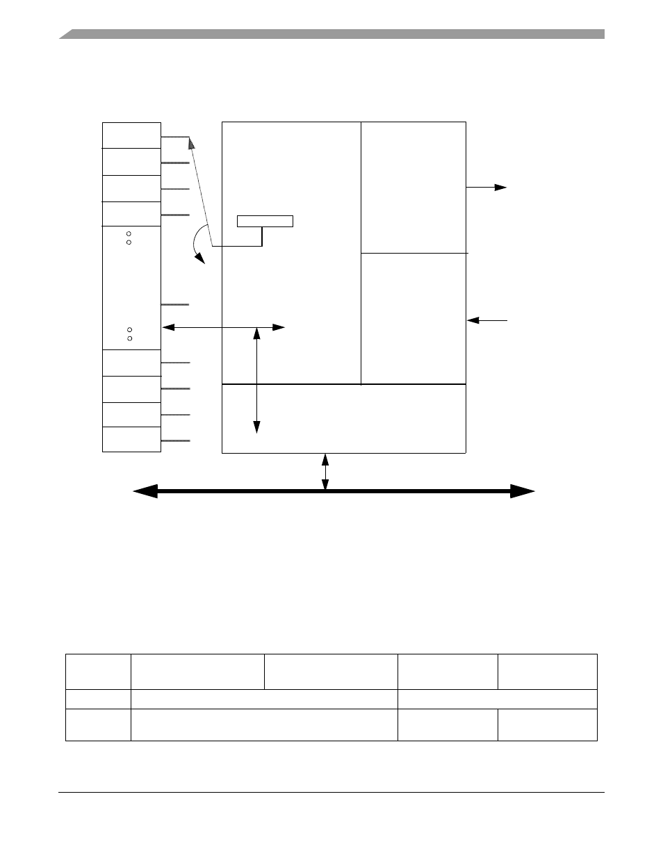
A block diagram describing the various submodules of the FlexCAN module is shown in
.
Each submodule is described in detail in subsequent sections.
Figure 25-1. FlexCAN Block Diagram and Pinout
25.1.1
FlexCAN Memory Map
The FlexCAN module address space is split into 128 bytes starting at the base address, and then an extra
256 bytes starting at the base address +128. The upper 256 are fully used for the message buffer structures,
as described in
Section 25.3.2, “Message Buffer Memory Map
.” Out of the lower 128 bytes, only part is
occupied by various registers.
Table 25-1. FlexCAN Memory Map
IPSBAR
Offset
[31:24]
[23:16]
[15:8]
[7:0]
0x1C_0000
Module Configuration Register (MCR)
Reserved
0x1C_0004
Reserved
Control Register 0
(CANCTRL0)
Control Register 1
(CANCTRL1)
MB0
MB2
MB1
MB3
MB12
MB14
MB13
MB15
0.25k/0.5KB
RAM
Bus Interface Unit
MB #
(0-15)
Transmitter
Receiver
Control
CANTX
CANRX
Internal Bus
MCF5282 and MCF5216 ColdFire Microcontroller User’s Manual, Rev. 3