Or less than v – Motorola ColdFire MCF5281 User Manual
Page 600
Queued Analog-to-Digital Converter (QADC)
28-62
Freescale Semiconductor
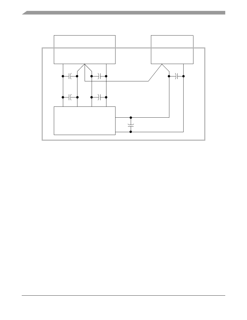
Figure 28-49. Star-Ground at the Point of Power Supply Origin
Other suggestions for PCB layout in which the QADC is employed include:
•
Analog ground must be low impedance to all analog ground points in the circuit.
•
Bypass capacitors should be as close to the power pins as possible.
•
The analog ground should be isolated from the digital ground. This can be done by cutting a
separate ground plane for the analog ground.
•
Non-minimum traces should be utilized for connecting bypass capacitors and filters to their
corresponding ground/power points.
•
Minimum distance for trace runs when possible.
28.9.5
Accommodating Positive/Negative Stress Conditions
Positive or negative stress refers to conditions which exceed nominally defined operating limits. Examples
include applying a voltage exceeding the normal limit on an input (for example, voltages outside of the
suggested supply/reference ranges) or causing currents into or out of the pin which exceed normal limits.
QADC specific considerations are voltages greater than V
DDA
or less than V
SSA
applied to an analog input
which cause excessive currents into or out of the input. Refer to
Chapter 33, “Electrical Characteristics
”
for more information on exact magnitudes.
Either stress conditions can potentially disrupt conversion results on neighboring inputs. Parasitic devices,
associated with CMOS processes, can cause an immediate disruptive influence on neighboring pins.
Common examples of parasitic devices are diodes to substrate and bipolar devices with the base terminal
tied to substrate (V
SS
/V
SSA
ground). Under stress conditions, current injected on an adjacent signal can
cause errors on the selected channel by developing a voltage drop across the selected channel’s
impedances.
QADC
V
RH
V
RL
V
SSA
V
DD
A
V
DD
V
SS
Analog Power Supply
+5 V
+5 V
AGND
Digital Power Supply
+5 V
PGND
PCB
MCF5282 and MCF5216 ColdFire Microcontroller User’s Manual, Rev. 3