Motorola ColdFire MCF5281 User Manual
Page 246
Signal Descriptions
14-6
Freescale Semiconductor
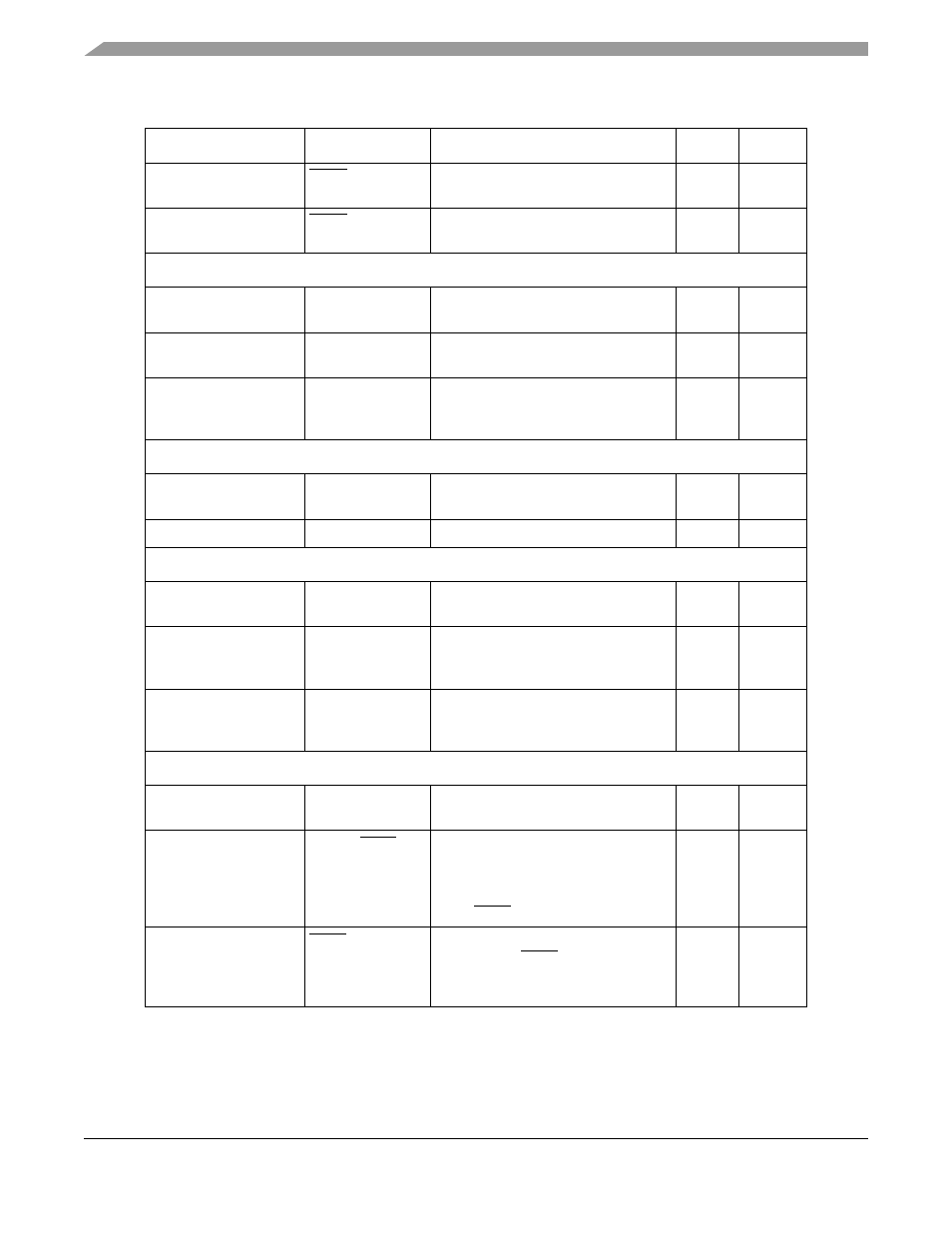
Clear-to-send
UCTS[1:0]
Signals UART that it can begin data
transmission.
I
Request to send
URTS[1:0]
Automatic UART request to send
outputs.
O
General Purpose Timer Signals
GPTA
GPTA[3:0]
Provide the external interface to the
timer A functions.
I/O
GPTB
GPTB[3:0]
Provide the external interface to the
timer B functions.
I/O
External clock input
SYNCA/SYNCB
Clear the timer’s clock, providing a
means of synchronization to externally
clocked or timed events.
I
DMA Timer Signals
DMA timer input
DTIN[3:0]
Clock the event counter or provide a
trigger to timer value capture logic.
I/O
DMA timer output
DTOUT[3:0]
Pulse or toggle on timer events.
I/O
Analog-to-Digital Converter (QADC) Signals
QADC analog input
AN[0:3]/AN[W:Z]
Direct analog input ANn, or
multiplexed input ANx.
I
QADC analog input
AN[52:53]/MA[0:1] Direct analog input ANn, or
multiplexed output MAn. MAn selects
the output of the external multiplexer.
I/O
QADC analog input
AN[55:56]/
TRIG[1:2]
Direct analog input ANn, or input
TRIGn. TRIGn causes one of the two
queues to execute.
I
Debug Support Signals
JTAG_EN
JTAG_EN
Selects between multiplexed debug
module and JTAG signals at reset.
I
Development serial
clock/Test reset
DSCLK/TRST
Development serial clock for the serial
interface to debug module (DSCLK).
Asynchronously resets the internal
JTAG controller to the test logic reset
state (TRST).
I
Breakpoint/
Test mode select
BKPT/TMS
Signals a hardware breakpoint in
debug mode (BKPT). Provides
information that determines JTAG test
operation mode (TMS).
I
Table 14-1. MCF5282 Signal Description (continued)
Signal Name
Abbreviation
Function
I/O
Page
MCF5282 and MCF5216 ColdFire Microcontroller User’s Manual, Rev. 3