2 reset configuration register (rcon), 2 reset configuration register (rcon) -5 – Motorola ColdFire MCF5281 User Manual
Page 533
Chip Configuration Module (CCM)
Freescale Semiconductor
27-5
27.5.3.2
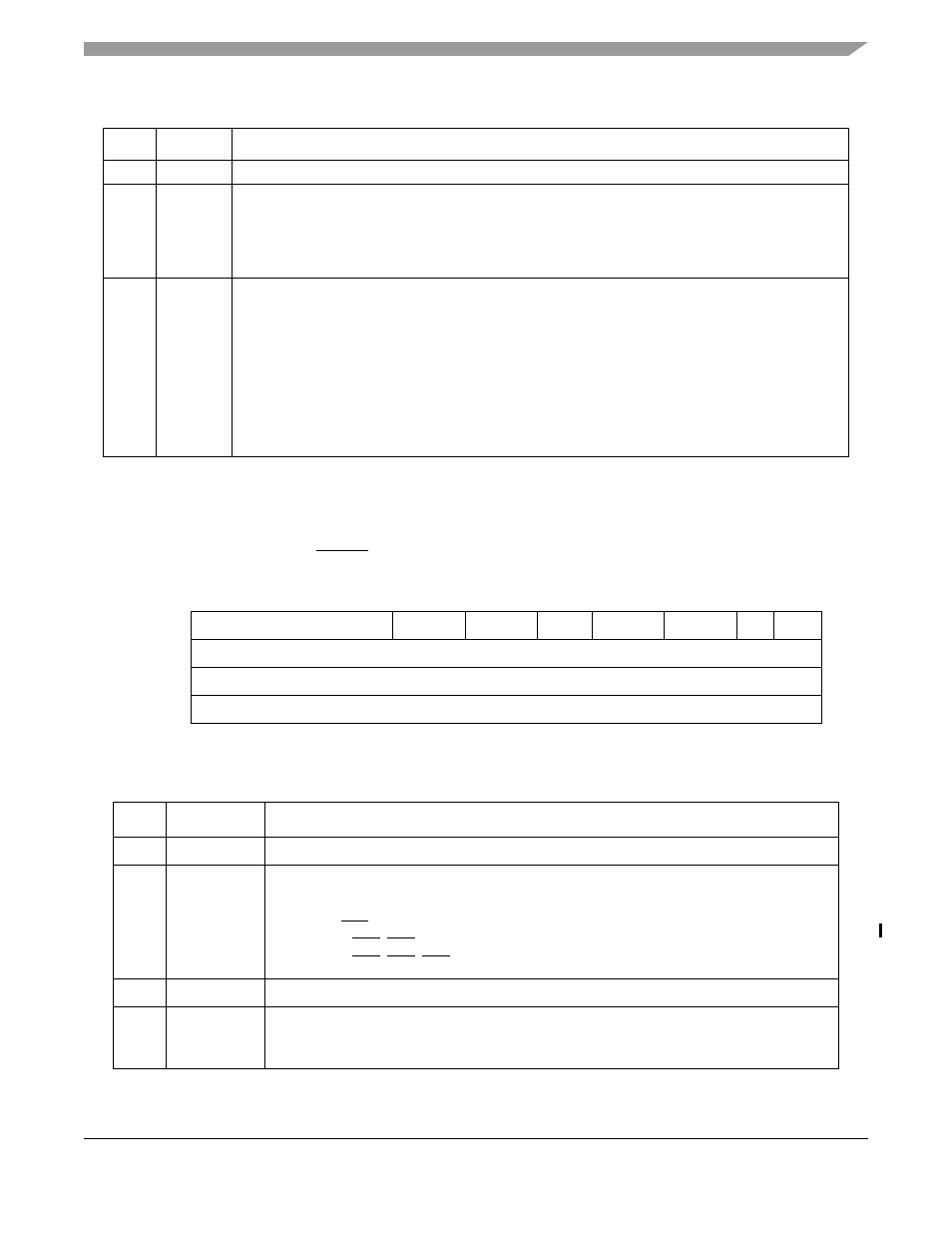
Reset Configuration Register (RCON)
At reset, RCON determines the default operation of certain chip functions. All default functions defined
by the RCON values can only be overridden during reset configuration (see
”) if the external RCON pin is asserted. RCON is a read-only register.
4
—
Reserved, should be cleared.
3
BME
Bus monitor enable. This read/write bit enables the bus monitor to operate during external bus
cycles.
0 Bus monitor disabled for external bus cycles.
1 Bus monitor enabled for external bus cycles.
shows the read/write accessibility of this write-once bit.
2–0
BMT
Bus monitor timing. This field selects the timeout period (in system clocks) for the bus monitor.
000 65536
001 32768
010 16384
011 8192
100 4096
101 2048
110 1024
111 512
shows the read/write accessibility of this write-once bit.
15
10
9
8
7
6
5
4
3
2
1
0
Field
—
RCSC
—
RLOAD BOOTPS BOOTSEL
—
MODE
Reset
0000_0000_1110_0000
R/W
R
Address
IPSBAR + 0x11_0008
Figure 27-3. Reset Configuration Register (RCON)
Table 27-5. RCON Field Descriptions
Bits
Name
Description
15–10
—
Reserved, should be cleared.
9–8
RCSC
Chip select configuration. Reflects the default chip select configuration. The default function
of the chip select configuration can be overridden during reset configuration.
00 PF[7:5] = A[23:21] (This is the value used for this device.)
01 PF[7] = CS6 / PF[6:5] = A[22:21]
10 PF[7:6] = CS6, CS5 / PF[5] = A[21]
11 PF[7:5] = CS6, CS5, CS4
7–6
—
Reserved, should be cleared.
5
RLOAD
Pad driver load. Reflects the default pad driver strength configuration.
0 Partial drive strength
1 Full drive strength (This is the value used for this device.)
Table 27-4. CCR Field Descriptions (continued)
Bits
Name
Description
MCF5282 and MCF5216 ColdFire Microcontroller User’s Manual, Rev. 3