Chapter 24 i2c interface, 1 introduction, 1 block diagram – Motorola ColdFire MCF5281 User Manual
Page 455: Chapter 24, 1 introduction -1, Chapter 24 i, C interface
Freescale Semiconductor
24-1
Chapter 24
I
2
C Interface
24.1
Introduction
This chapter describes the I
2
C module, clock synchronization, and I
2
C programming model registers. It
also provides extensive programming examples.
24.1.1
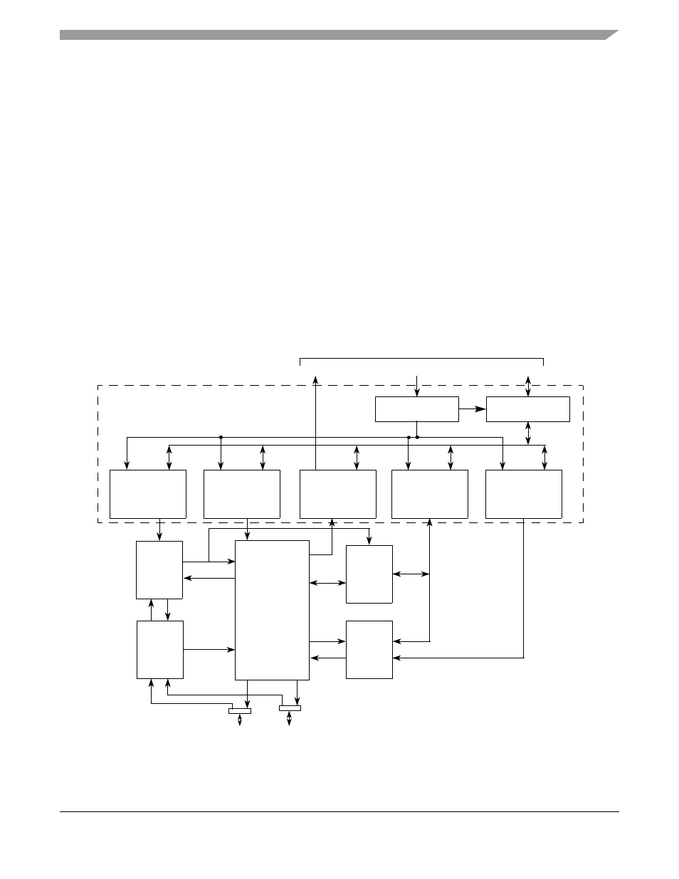
Block Diagram
2
C module block diagram, illustrating the interaction of the registers described in
Section 24.2, “Memory Map/Register Definition”.
Figure 24-1. I
2
C Module Block Diagram
Address
Compare
In/Out
Data
Shift
Start, Stop,
Input
Sync
Clock
Control
Registers and Slave Interface
Address Decode
I
2
C Address
Data MUX
Address
IRQ
Data
and
Arbitration
Control
Register
Internal Bus
Register
I
2
C Frequency
Divider Register
I
2
C Data
I/O Register
I
2
C Status
Register
I
2
C Control
Register
I2C_SCL
I2C_SDA
(I2FDR)
(I2CR)
(I2SR)
(I2DR)
(I2ADR)
MCF5282 and MCF5216 ColdFire Microcontroller User’s Manual, Rev. 3