6 register descriptions, 1 qadc module configuration register (qadcmcr), 6 register descriptions -7 – Motorola ColdFire MCF5281 User Manual
Page 545: 1 qadc module configuration register (qadcmcr) -7
Queued Analog-to-Digital Converter (QADC)
Freescale Semiconductor
28-7
28.6
Register Descriptions
This subsection describes the QADC registers.
28.6.1
QADC Module Configuration Register (QADCMCR)
The QADCMCR contains bits that control QADC debug and stop modes and determine the privilege level
required to access most registers.
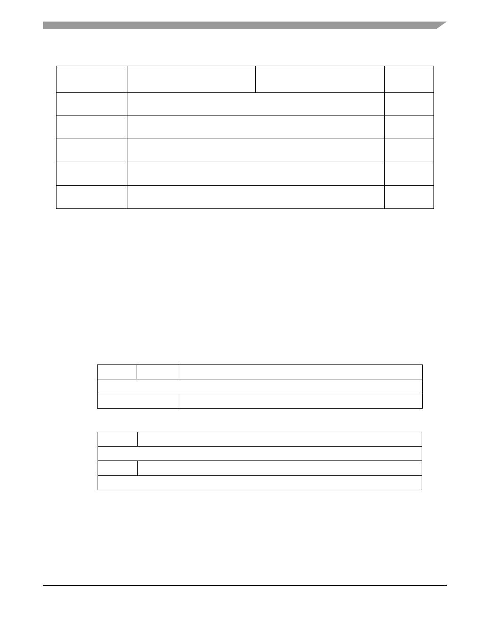
0x19_0014–
0x19_01fe
Reserved
(3)
—
0x19_0200–
0x19_027e
Conversion Command Word Table (CCW)
S/U
0x19_0280–
0x19_02fe
Right Justified, Unsigned Result Register (RJURR)
S/U
0x19_0300–
0x19_037e
Left Justified, Signed Result Register (LJSRR)
S/U
0x19_0380–
0x19_03fe
Left Justified, Unsigned Result Register (LJURR)
S/U
1
S = CPU supervisor mode access only. S/U = CPU supervisor or user mode access. User mode accesses to
supervisor only addresses have no effect and result in a cycle termination transfer error.
2
Access results in the module generating an access termination transfer error if not in test mode.
3
Read/writes have no effect and the access terminates with a transfer error exception.
15
14
13
8
Field
QSTOP
QDBG
—
Reset
0000_0000
R/W:
R/W
R
7
6
0
Field
SUPV
—
Reset
1000_0000
R/W:
R/W
R
Address
IPSBAR + 0x19_0000, 0x19_0001
Figure 28-3. QADC Module Configuration Register (QADCMCR)
Table 28-2. QADC Memory Map (continued)
IPSBAR +
Offset
MSB
LSB
Access
1
MCF5282 and MCF5216 ColdFire Microcontroller User’s Manual, Rev. 3