13 fast ethernet ac timing specifications, 13fast ethernet ac timing specifications -21, Figure 33-10 – Motorola ColdFire MCF5281 User Manual
Page 705
Electrical Characteristics
Freescale Semiconductor
33-21
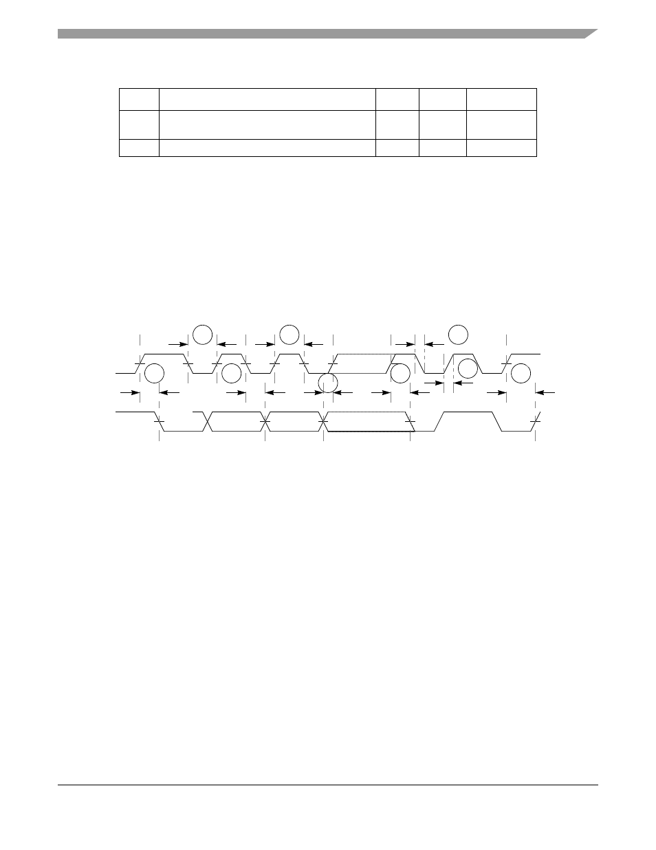
shows timing for the values in
Figure 33-10. I
2
C Input/Output Timings
33.13 Fast Ethernet AC Timing Specifications
MII signals use TTL signal levels compatible with devices operating at either 5.0 V or 3.3 V.
NOTE
The MCF5214 and MCF5216 do not contain an FEC module.
33.13.1 MII Receive Signal Timing (ERXD[3:0], ERXDV, ERXER, and ERXCLK)
The receiver functions correctly up to a ERXCLK maximum frequency of 25 MHz +1%. There is no
minimum frequency requirement. In addition, the processor clock frequency must exceed twice the
ERXCLK frequency.
lists MII receive channel timings.
Start condition setup time (for repeated start
condition only)
20
—
Bus clocks
Stop condition setup time
10
—
Bus clocks
1
Note: Output numbers depend on the value programmed into the IFDR; an IFDR programmed
with the maximum frequency (IFDR = 0x20) results in minimum output timings as shown in
. The I
2
C interface is designed to scale the actual data transition time to move it to
the middle of the SCL low period. The actual position is affected by the prescale and division
values programmed into the IFDR; however, the numbers given in
values.
2
Because SCL and SDA are open-collector-type outputs, which the processor can only actively
drive low, the time SCL or SDA take to reach a high level depends on external signal capacitance
and pull-up resistor values.
3
Specified at a nominal 50-pF load.
Table 33-20. I
2
C Output Timing Specifications between SCL and SDA (continued)
Num
Characteristic
Min
Max
Units
I2
I6
I1
I4
I7
I8
I9
I5
I3
SCL
SDA
MCF5282 and MCF5216 ColdFire Microcontroller User’s Manual, Rev. 3