Motorola ColdFire MCF5281 User Manual
Page 690
Electrical Characteristics
33-6
Freescale Semiconductor
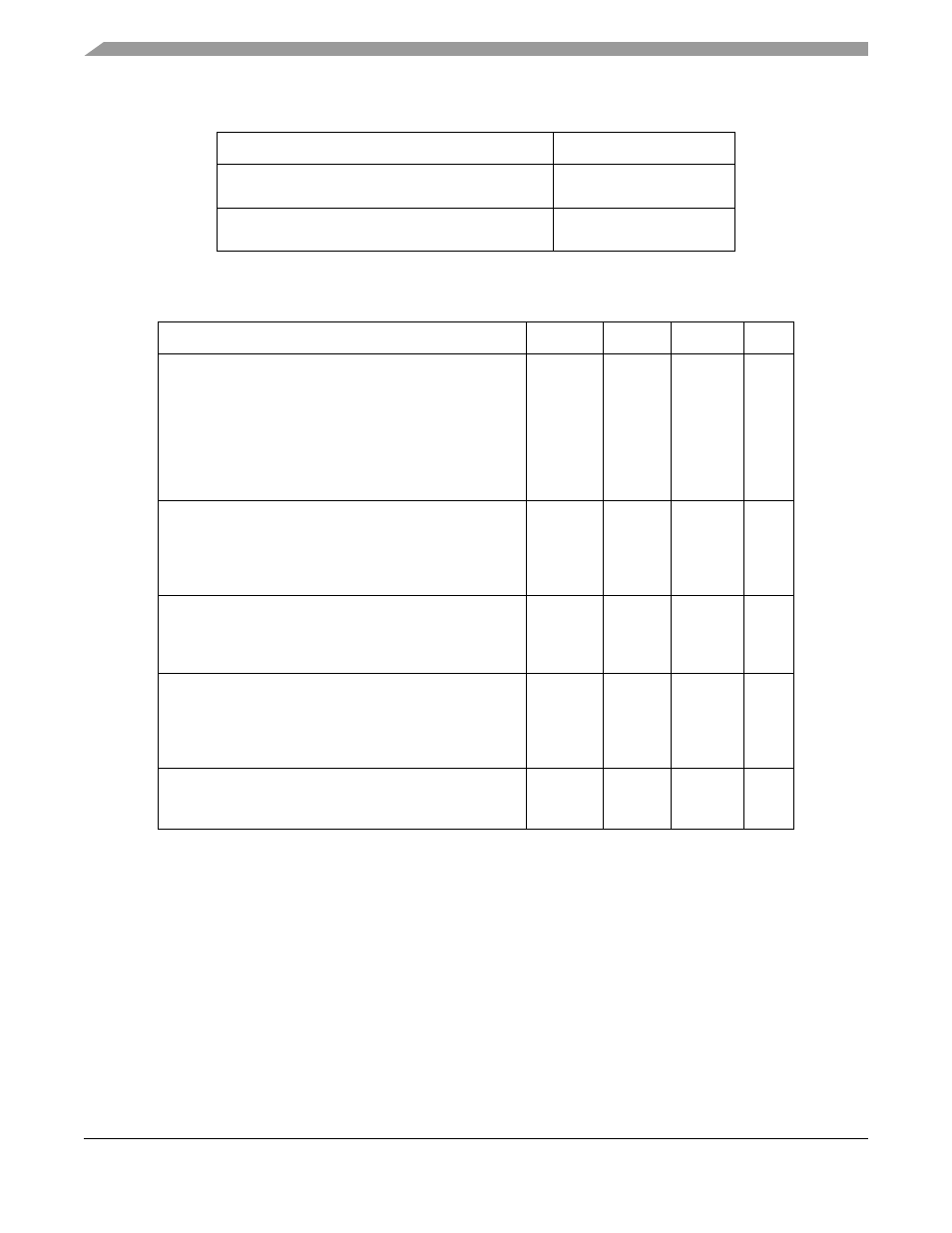
lists the maximum power consumption specifications.
Table 33-6. Typical Application Power Consumption
Application
Current
Dhrystone benchmark running from cache and
on-chip SRAM (running at 64 MHz f
sys
)
181.6 mA
dBUG ROM monitor running from external flash and
SDRAM (running at 64 MHz f
sys
)
155 mA
Table 33-7. Maximum Power Consumption Specifications
Characteristic
Symbol
Typical
Max
Unit
Operating Supply Current
1
Master Mode
• 66 MHz
• 80 MHz (MCF528x only)
Single Chip Mode
WAIT/DOZE
• 66 MHz
• 80 MHz (MCF528x only)
1
Current measured at maximum system clock frequency, all modules active, and default drive
strength with matching load.
I
DD
—
—
—
—
—
—
200
240
150
125
150
mA
mA
mA
mA
mA
Clock Synthesizer Supply Current
Normal Operation 8.25 MHz crystal, VCO on, Max f
sys
STOP (OSC and PLL enabled)
STOP (OSC enable, PLL disabled)
STOP (OSC and PLL disabled)
I
DDPLL
—
—
—
—
4
2
1
10
mA
mA
mA
μ
A
RAM Memory Standby Supply Current
Normal Operation: V
DD
> V
STBY
- 0.3 V
Transient Condition: V
STBY
- 0.3 V > V
DD
> V
SS
+ 0.5 V
Standby Operation: V
DD
< V
SS
+ 0.5 V
I
STBY
—
—
—
10
7
20
μ
A
mA
μ
A
Flash Memory Supply Current
Read
Program or Erase
2
Idle
STOP
2
Programming and erasing all 8 blocks of the Flash.
I
DDF
16.5
3
25
4
0.2
3
Measured with f
sys
of 64 MHz.
4
Measured with f
sys
of 32 MHz and f
clk
of 187.5 kHz.
30
64
20
10
mA
mA
mA
μ
A
Analog Supply Current
Normal Operation
Low-Power Stop
I
DDA
—
—
5.0
10.0
mA
μ
A
MCF5282 and MCF5216 ColdFire Microcontroller User’s Manual, Rev. 3