5 edge port pin data register (eppdr), 6 edge port flag register (epfr) – Motorola ColdFire MCF5281 User Manual
Page 214
Edge Port Module (EPORT)
11-6
Freescale Semiconductor
11.4.2.5
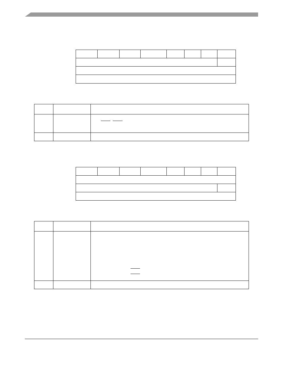
Edge Port Pin Data Register (EPPDR)
11.4.2.6
Edge Port Flag Register (EPFR)
7
6
5
4
3
2
1
0
Field
EPPD7
EPPD6
EPPD5
EPPD4
EPPD3 EPPD2 EPPD1
—
Reset
Current pin state
0
R/W
R
Address
IPSBAR + 0x0013_0005
Figure 11-6. EPORT Port Pin Data Register (EPPDR)
Table 11-7. EPPDR Field Descriptions
Bit(s)
Name
Description
7–1
EPPDx
Edge port pin data bits. The read-only EPPDR reflects the current state of the EPORT
pins IRQ7–IRQ1. Writing to EPPDR has no effect, and the write cycle terminates
normally. Reset does not affect EPPDR.
0
—
Reserved, should be cleared.
7
6
5
4
3
2
1
0
Field
EPF7
EPF6
EPF5
EPF4
EPF3
EPF2
EPF1
—
Reset
0000_0000
R/W
R/W
R
Address
IPSBAR + 0x0013_0006
Figure 11-7. EPORT Port Flag Register (EPFR)
Table 11-8. EPFR Field Descriptions
Bit(s)
Name
Description
7–1
EPFx
Edge port flag bits. When an EPORT pin is configured for edge triggering, its
corresponding read/write bit in EPFR indicates that the selected edge has been
detected. Reset clears EPF7-EPF1.
Bits in this register are set when the selected edge is detected on the corresponding
pin. A bit remains set until cleared by writing a 1 to it. Writing 0 has no effect. If a pin
is configured as level-sensitive (EPPARx = 00), pin transitions do not affect this
register.
1 Selected edge for IRQx pin has been detected.
0 Selected edge for IRQx pin has not been detected.
0
—
Reserved, should be cleared.
MCF5282 and MCF5216 ColdFire Microcontroller User’s Manual, Rev. 3