2 the can system, 3 message buffers, 1 message buffer structure – Motorola ColdFire MCF5281 User Manual
Page 474: 2 the can system -4 25.3 message buffers -4, 1 message buffer structure -4
FlexCAN
25-4
Freescale Semiconductor
25.2
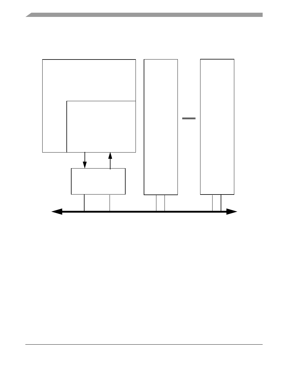
The CAN System
A typical CAN system is shown below in
Figure 25-2. Typical CAN system
Each CAN station is connected physically to the CAN bus through a transceiver. The transceiver provides
the transmit drive, waveshaping, and receive/compare functions required for communicating on the CAN
bus. It can also provide protection against damage to the FlexCAN caused by a defective CAN bus or
defective stations.
25.3
Message Buffers
25.3.1
Message Buffer Structure
shows the extended (29 bit) ID message buffer structure.
displays the standard (11
bit) ID message buffer structure.
CAN Bus
FlexCAN
CANRX
Transceiver
CAN Station 1
CAN Station 2
CAN Station n
CANTX
ColdFire Processor
MCF5282 and MCF5216 ColdFire Microcontroller User’s Manual, Rev. 3