Motorola ColdFire MCF5281 User Manual
Page 162
System Control Module (SCM)
8-10
Freescale Semiconductor
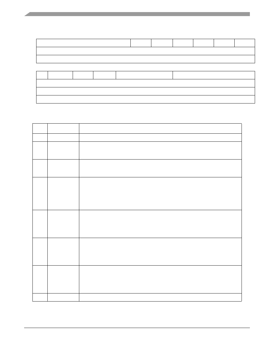
31
26
25
24
23
22
21
20
19
18
17
16
Field
—
M2_P_EN BCR24BIT M3_PRTY M2_PRTY M0_PRTY M1_PRTY
Reset
0011_0000_1110_0001
R/W
R/W
15
14
13
12
11
8
7
0
Field
—
FIXED
TIMEOUT PRKLAST
LCKOUT_TIME
—
Reset
0000_0000_0000_0000
R/W
R/W
Address
IPSBAR + 0x01C
Figure 8-7. Default Bus Master Park Register (MPARK)
Table 8-6. MPARK Field Description
Bits
Name
Description
31–26
—
Reserved, should be cleared.
25
M2_P_EN
DMA bandwith control enable
0 disable the use of the DMA's bandwidth control to elevate the priority of its bus requests.
1 enable the use of the DMA's bandwidth control to elevate the priority of its bus requests.
24
BCR24BIT
Enables the use of 24 bit byte count registers in the DMA module
0 DMA BCRs function as 16 bit counters.
1 DMA BCRs function as 24 bit counters.
23–22
M3_PRTY
Master priority level for master 3 (Fast Ethernet Controller)
00 fourth (lowest) priority
01 third priority
10 second priority
11 first (highest) priority
Note: Reserved on the MCF5214 and MCF5216
21–20
M2_PRTY
Master priority level for master 2 (DMA Controller)
00 fourth (lowest) priority
01 third priority
10 second priority
11 first (highest) priority
19–18
M0_PRTY
Master priority level for master 0 (ColdFire Core)
00 fourth (lowest) priority
01 third priority
10 second priority
11 first (highest) priority
17–16
M1_PRTY
Master priority level for master 1 (Not used in user mode)
00 fourth (lowest) priority
01 third priority
10 second priority
11 first (highest) priority
15
—
Reserved, should be cleared.
MCF5282 and MCF5216 ColdFire Microcontroller User’s Manual, Rev. 3