3 byte count registers (bcr0-bcr3), 4 dma control registers (dcr0-dcr3), 0) [p. 16-7 – Motorola ColdFire MCF5281 User Manual
Page 303: 1) [p. 16-7, P. 16-7, 2) [p. 16-7, 3) [p. 16-7, 3 byte count registers (bcr0–bcr3), 4 dma control registers (dcr0–dcr3)
DMA Controller Module
Freescale Semiconductor
16-7
16.4.3
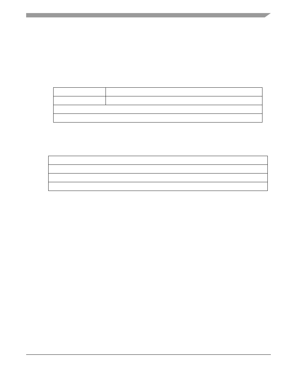
Byte Count Registers (BCR0–BCR3)
BCRn, shown in
and
, hold the number of bytes yet to be transferred for a given
block. The offset within the memory map is based on the value of MPARK[BCR24BIT]. BCRn
decrements on the successful completion of the address transfer of a write transfer. BCRn decrements by
1, 2, 4, or 16 for byte, word, longword, or line accesses, respectively.
shows BCRn for BCR24BIT = 1.
Figure 16-6. Byte Count Registers (BCRn)—BCR24BIT = 1
shows BCRn for BCR24BIT = 0.
Figure 16-7. Byte Count Registers (BCRn)—BCR24BIT = 0
DSRn[DONE], shown in
, is set when the block transfer is complete.
When a transfer sequence is initiated and BCRn[BCR] is not a multiple of 16, 4, or 2 when the DMA is
configured for line, longword, or word transfers, respectively, DSRn[CE] is set and no transfer occurs. See
Section 16.4.5, “DMA Status Registers (DSR0–DSR3)
.”
16.4.4
DMA Control Registers (DCR0–DCR3)
DCRn, shown in
, is used for configuring the DMA controller module. Note that DCRn[AT] is
available only if MPARK[BCR24BIT] is set. See
Section 8.5.3, “Bus Master Park Register (MPARK)
more information.
31
24 23
0
Field
—
BCR
Reset
—
0000_0000_0000_0000_0000_0000
R/W
R/W
Address
IPSBAR + 0x10C, 0x14C, 0x18C, 0x1CC
15
0
Field
BCR
Reset
0000_0000_0000_0000
R/W
R/W
Address
IPSBAR + 0x10C, 0x14C, 0x18C, 0x1CC
MCF5282 and MCF5216 ColdFire Microcontroller User’s Manual, Rev. 3