Motorola ColdFire MCF5281 User Manual
Page 408
Queued Serial Peripheral Interface (QSPI)
22-4
Freescale Semiconductor
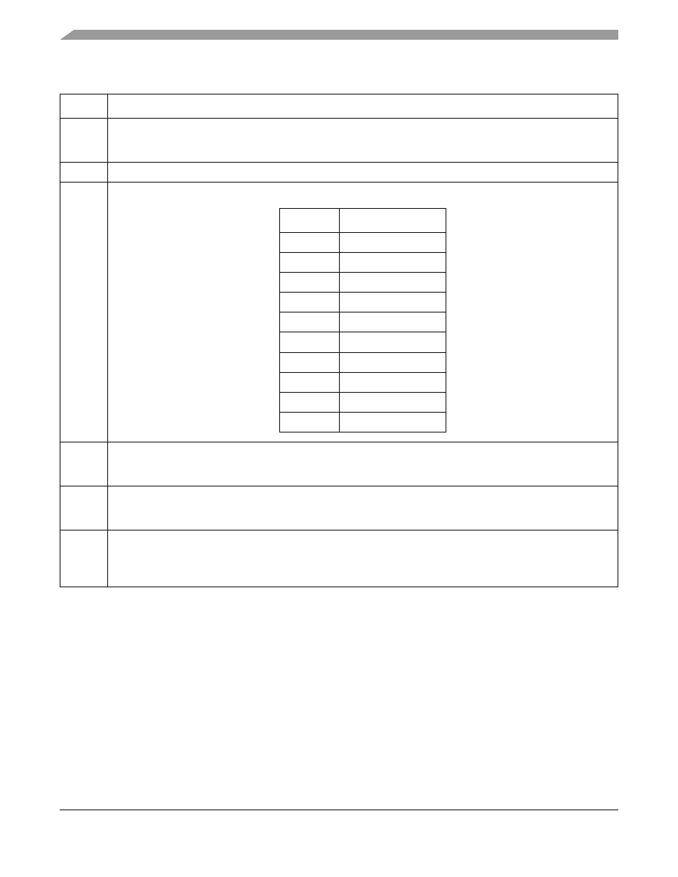
Table 22-3. QMR Field Descriptions
Field
Description
15
MSTR
Master mode enable.
0 Reserved, do not use.
1 The QSPI is in master mode. Must be set for the QSPI module to operate correctly.
14
Reserved, must be cleared.
13–10
BITS
Transfer size. Determines the number of bits to be transferred for each entry in the queue.
9
CPOL
Clock polarity. Defines the clock polarity of QSPI_CLK.
0 The inactive state value of QSPI_CLK is logic level 0.
1 The inactive state value of QSPI_CLK is logic level 1.
8
CPHA
Clock phase. Defines the QSPI_CLK clock-phase.
0 Data captured on the leading edge of QSPI_CLK and changed on the following edge of QSPI_CLK.
1 Data changed on the leading edge of QSPI_CLK and captured on the following edge of QSPI_CLK.
7–0
BAUD
Baud rate divider. The baud rate is selected by writing a value in the range 2–255. A value of zero disables the QSPI.
A value of 1 is an invalid setting. The desired QSPI_CLK baud rate is related to the internal bus clock and
QMR[BAUD] by the following expression:
QMR[BAUD] = f
sys/
/ (2 ×
[desired QSPI_CLK baud rate])
BITS
Bits per Transfer
0000
16
0001–0111
Reserved
1000
8
1001
9
1010
10
1011
11
1100
12
1101
13
1110
14
1111
15
MCF5282 and MCF5216 ColdFire Microcontroller User’s Manual, Rev. 3