3 mii async inputs signal timing (ecrs and ecol), Figure 33-12 – Motorola ColdFire MCF5281 User Manual
Page 707
Electrical Characteristics
Freescale Semiconductor
33-23
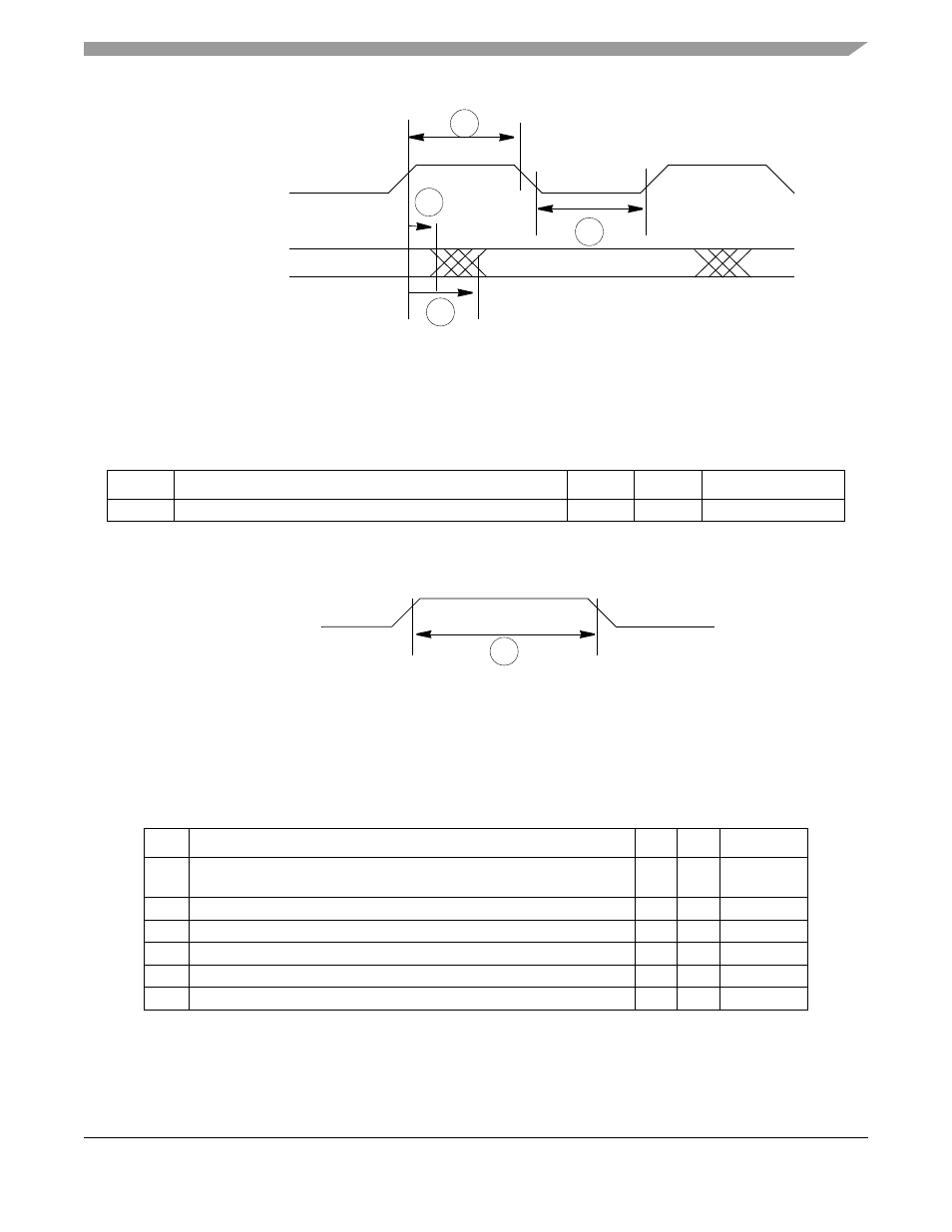
Figure 33-12. MII Transmit Signal Timing Diagram
33.13.3 MII Async Inputs Signal Timing (ECRS and ECOL)
lists MII asynchronous inputs signal timing.
shows MII asynchronous input timings listed in
.
Figure 33-13. MII Async Inputs Timing Diagram
33.13.4 MII Serial Management Channel Timing (EMDIO and EMDC)
The FEC functions correctly with a maximum MDC frequency of 2.5 MHz.
lists MII serial
management channel timings.
shows MII serial management channel timings listed in
.
Table 33-23. MII Async Inputs Signal Timing
Num
Characteristic
Min
Max
Unit
M9
1
1
ECOL has the same timing in 10 Mbit 7-wire interface mode.
ECRS, ECOL minimum pulse width
1.5
—
ETXCLK period
Table 33-24. MII Serial Management Channel Timing
Num
Characteristic
Min
Max
Unit
M10
EMDC falling edge to EMDIO output invalid (minimum propagation
delay)
0
—
ns
M11
EMDC falling edge to EMDIO output valid (max prop delay)
—
25
ns
M12
EMDIO (input) to EMDC rising edge setup
10
—
ns
M13
EMDIO (input) to EMDC rising edge hold
0
—
ns
M14
EMDC pulse width high
40%
60%
MDC period
M15
EMDC pulse width low
40%
60%
MDC period
M6
ETXCLK (input)
ETXD[3:0] (outputs)
ETXEN
ETXER
M5
M7
M8
ECRS, ECOL
M9
MCF5282 and MCF5216 ColdFire Microcontroller User’s Manual, Rev. 3