6 free running timer (timer), 7 rx mask registers – Motorola ColdFire MCF5281 User Manual
Page 493
FlexCAN
Freescale Semiconductor
25-23
25.5.6
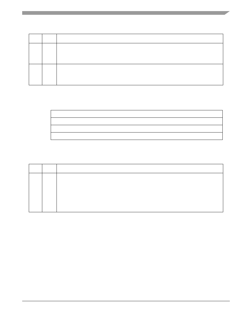
Free Running Timer (TIMER)
25.5.7
Rx Mask Registers
These registers are used as acceptance masks for received frame IDs. 3 masks are defined: A global mask,
used for Rx buffers 0-13, and 2 more separate masks for buffers 14 and 15.
Mask bit = 0: The corresponding incoming ID bit is “don’t care”.
Mask bit = 1: The corresponding ID bit is checked against the incoming ID bit, to see if a match exists.
Note that these masks are used both for Standard and Extended ID formats. The value of mask registers
should NOT be changed while in normal operation, as locked frames which matched a MB through a mask,
may be transferred into the MB (upon release) but may no longer match.
5–3
PSEG
1
PSEG1[2:0] — Phase buffer segment 1. The PSEG1 field defines the length of phase buffer segment
1 in the bit time. The valid programmed values are 0 through 7.
The length of phase buffer segment 1 is calculated as follows:
Phase Buffer Segment 1 = (PSEG1 + 1) Time Quanta
2–0
PSEG
2
PSEG2 — Phase Buffer Segment 2. The PSEG2 field defines the length of phase buffer segment 2
in the bit time. The valid programmed values are 0 through 7.
The length of phase buffer segment 2 is calculated as follows:
Phase Buffer Segment 2 = (PSEG2 + 1) Time Quanta
15
0
Field
TIMER
Reset
0000_0000_0000_0000
R/W
R/W
Address
IPSBAR + 0x1C_000A
Figure 25-11. Free Running Timer (TIMER)
Table 25-14. TIMER Field Descriptions
Bits
Name
Description
15–0
TIMER The free running timer counter can be read and written by the CPU. The timer starts from zero after
reset, counts linearly to 0xFFFF, and wraps around.
The timer is clocked by the FlexCAN bit-clock. During a message, it increments by one for each bit
that is received or transmitted. When there is no message on the bus, it increments at the nominal bit
rate.
The timer value is captured at the beginning of the identifier field of any frame on the CAN bus. The
captured value is written into the “time stamp” entry in a message buffer after a successful reception
or transmission of a message.
Table 25-13. CANCTRL2 Field Descriptions (continued)
Bits
Name
Description
MCF5282 and MCF5216 ColdFire Microcontroller User’s Manual, Rev. 3