2 low-power control register (lpcr), 2 low-power control register (lpcr) -4 – Motorola ColdFire MCF5281 User Manual
Page 140
Power Management
7-4
Freescale Semiconductor
7.2.3.2
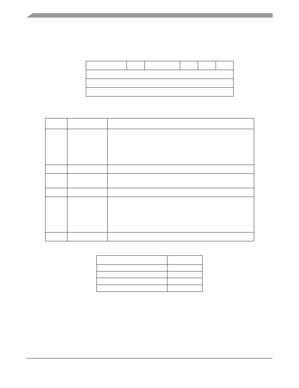
Low-Power Control Register (LPCR)
The LPCR controls chip operation and module operation during low-power modes.
7
6
5
4
3
2
1
0
Field
LPMD
—
STPMD
—
LVDSE
—
Reset
0000_0010
R/W
R/W
Address
IPSBAR + 0x0011_0007
Figure 7-2. Low-Power Control Register (LPCR)
Table 7-4. LPCR Field Descriptions
Bits
Name
Description
7–6
LPMD
Low-power mode select. Used to select the low-power mode the chip
enters once the ColdFire CPU executes the STOP instruction. These bits
must be written prior to instruction execution for them to take effect. The
LPMD[1:0] bits are readable and writable in all modes.
illustrates
the four different power modes that can be configured with the LPMD bit
field.
5
—
Reserved, should be cleared.
4–3
STPMD
PLL/CLKOUT stop mode. Controls PLL and CLKOUT operation in stop
mode as shown in
2
—
Reserved, should be cleared.
1
LVDSE
LDV standby enable. Controls whether the PMM enters VREG Standby
Mode (LVD disabled) or VREG Pseudo-Standby (LVD enabled) mode when
the PMM receives a power down request. This bit has no effect if the
RCR[LVDE] bit is a logic 0.
1 VREG Pseudo-Standby mode (LVD enabled on power down request).
0 VREG Standby mode (LVD disabled on power down request).
0
—
Reserved, should be cleared.
Table 7-5. Low-Power Modes
LPMD[1:0]
Mode
11
STOP
10
WAIT
01
DOZE
00
RUN
MCF5282 and MCF5216 ColdFire Microcontroller User’s Manual, Rev. 3