5 fast termination cycles, 5 fast termination cycles -8, Figure 13-8 – Motorola ColdFire MCF5281 User Manual
Page 232
External Interface Module (EIM)
13-8
Freescale Semiconductor
The write cycle timing diagram is shown in
.
Figure 13-8. Basic Write Bus Cycle
describes the six states of a basic write cycle.
13.4.5
Fast Termination Cycles
Two clock cycle transfers are supported on the external bus. In most cases, this is impractical to use in a
system because the termination must take place in the same half-clock during which TS is asserted. As this
is atypical, it is not referred to as the zero-wait-state case but is called the fast-termination case. Fast
termination cycles occur when the external device or memory asserts TA less than one clock after TS is
asserted. This means that the processor samples TA on the rising edge of the second cycle of the bus
transfer.
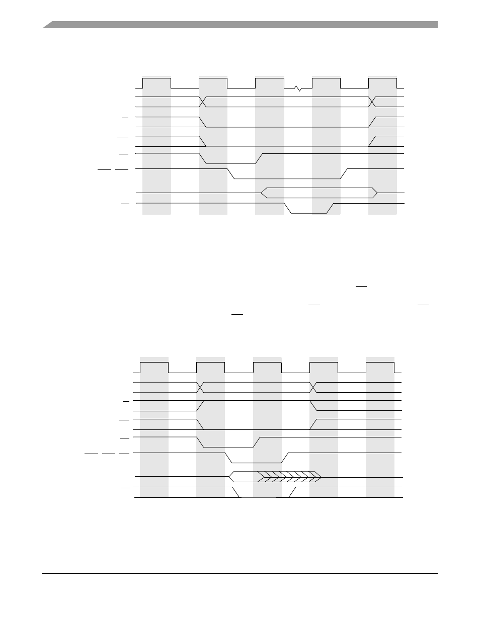
shows a read cycle with fast termination. Note that fast termination cannot be used
with internal termination.
Figure 13-9. Read Cycle with Fast Termination
shows a write cycle with fast termination.
R/W
TIP
TS
D[31:0]
TA
S0
S1
S2
S3
S4
S5
Write
CLKOUT
CSn, BSn
A[31:0], SIZ[1:0]
R/W
TIP
TS
D[31:0]
TA
S0
S1
S4
S5
Read
CLKOUT
CSn, BSn, OE
A[31:0], SIZ[1:0]
MCF5282 and MCF5216 ColdFire Microcontroller User’s Manual, Rev. 3