Chapter 16 dma controller module, 1 overview, Chapter 16 – Motorola ColdFire MCF5281 User Manual
Page 297: Dma controller module, 1 overview -1
Freescale Semiconductor
16-1
Chapter 16
DMA Controller Module
This chapter describes the direct memory access (DMA) controller module. It provides an overview of the
module and describes in detail its signals and registers. The latter sections of this chapter describe
operations, features, and supported data transfer modes in detail.
NOTE
The designation “n” is used throughout this section to refer to registers or
signals associated with one of the four identical DMA channels: DMA0,
DMA1, DMA2 or DMA3.
16.1
Overview
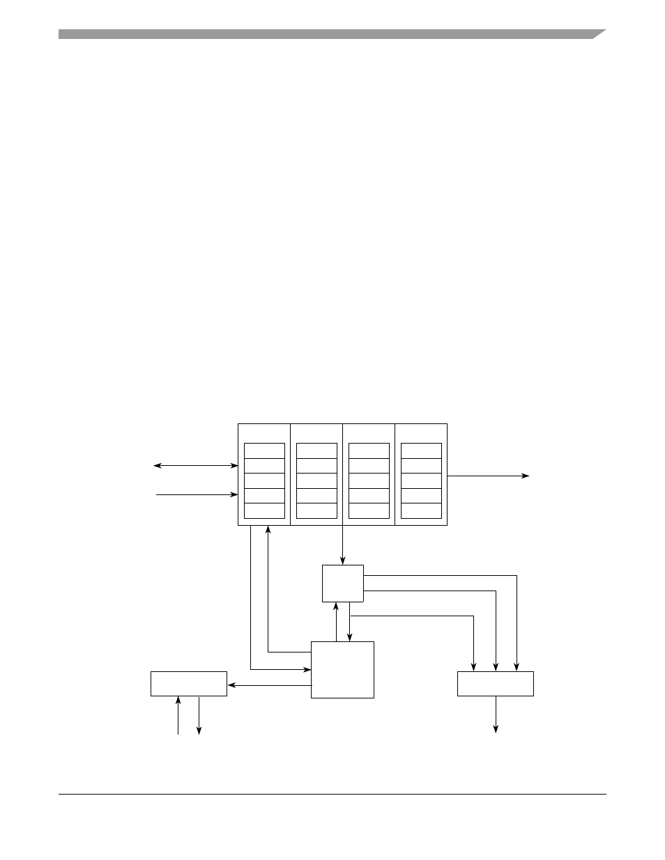
The DMA controller module provides an efficient way to move blocks of data with minimal processor
interaction. The DMA module, shown in
, provides four channels that allow byte, word,
longword, or 16-byte burst data transfers. Each channel has a dedicated source address register (SARn),
destination address register (DARn), byte count register (BCRn), control register (DCRn), and status
register (DSRn). Transfers are dual address to on-chip devices, such as UART, SDRAM controller, and
GPIOs.
Figure 16-1. DMA Signal Diagram
MUX
Arbitration/
Bus Interface
Data Path
Control
Internal
External
Channel
Channel
MUX
Registered
Data Path
SAR0
DAR0
BCR0
DCR0
DSR0
Channel 0
Interrupts
SAR1
DAR1
BCR1
DCR1
DSR1
Channel 1
SAR2
DAR2
BCR2
DCR2
DSR2
Channel 2
SAR3
DAR3
BCR3
DCR3
DSR3
Channel 3
Bus
Requests
Attributes
Current Master Attributes
Write Data Bus
Read Data Bus
System Bus Address
System Bus Size
Channel
Enables
Requests
Bus Signals
Control
Control
MCF5282 and MCF5216 ColdFire Microcontroller User’s Manual, Rev. 3