1 reset configuration, 1 reset configuration -7, Determined during reset (see – Motorola ColdFire MCF5281 User Manual
Page 535: Table 27-8, Dden during reset configuration (see, Section 27.6.1, “reset, Configuration
Chip Configuration Module (CCM)
Freescale Semiconductor
27-7
5. Clock mode selections
6. Chip select configuration
These functions are described here.
27.6.1
Reset Configuration
During reset, the pins for the reset override functions are immediately configured to known states.
shows the states of the external pins while in reset.
If the RCON pin is not asserted during reset, the chip configuration and the reset configuration pin
functions after reset are determined by the RCON register or fixed defaults, regardless of the states of the
external data pins. The internal configuration signals are driven to levels specified by the RCON register’s
reset state for default module configuration.
If the RCON pin is asserted during reset, then various chip functions, including the reset configuration pin
functions after reset, are configured according to the levels driven onto the external data pins. (See
) The internal configuration signals are driven to reflect the levels on the external configuration
pins to allow for module configuration.
NOTE
During reset, the CLKMOD pins always determine the clock mode,
regardless of the RCON pin state.
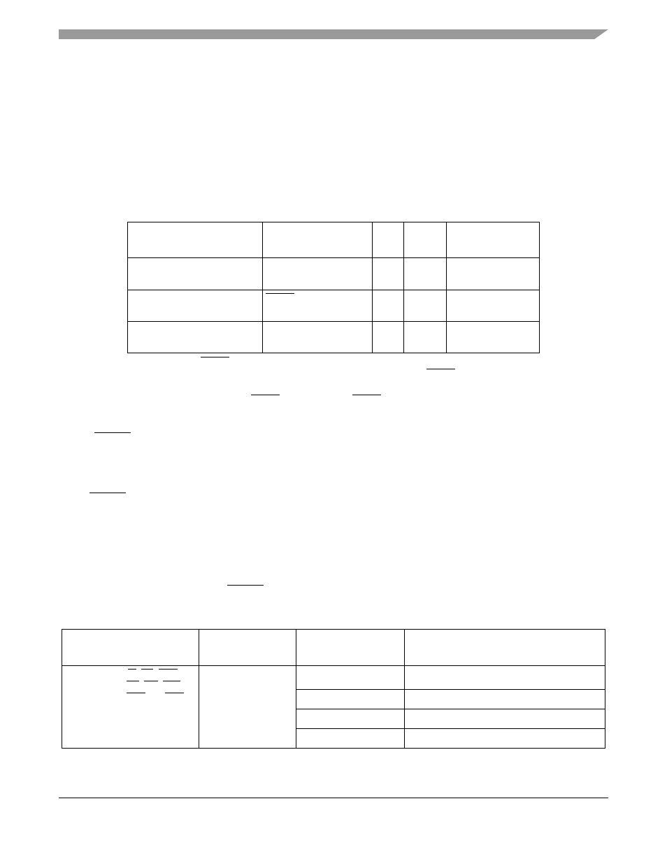
Table 27-7. Reset Configuration Pin States During Reset
Pin
Pin
Function
1
1
If the external RCON pin is not asserted during reset, pin functions are determined by the
default operation mode defined in the RCON register. If the external RCON pin is asserted, pin
functions are determined by the override values driven on the external data bus pins.
I/O
Output
State
Input
State
D[26:24, 21, 19:16],
PA[2:0], PB[5, 3:0]
Digital I/O or primary
function
Input
—
Must be driven
by external logic
RCON
RCON function for all
modes
2
2
During reset, the external RCON pin assumes its RCON pin function, but this pin changes to
the function defined by the chip operation mode immediately after reset. See
Input
—
Internal weak
pull-up device
CLKMOD1, CLKMOD0
Not affected
Input
—
Must be driven by
external logic
Table 27-8. Configuration During Reset
1
Pin(s) Affected
Default
Configuration
Override Pins
in Reset
2,34
Function
D[31:0], R/W, TA, TEA,
TSIZ[1:0], TS, TIP, OE,
A[23:0], BS[3:0], CS[3:0]
RCON0 = 0
D[26,17:16]
Chip Mode Selected
111
Master mode
110
Single-chip mode
5
100 or 0xx
Reserved
MCF5282 and MCF5216 ColdFire Microcontroller User’s Manual, Rev. 3