6 pll loss of lock conditions, 6 pll loss of lock conditions -14 – Motorola ColdFire MCF5281 User Manual
Page 184
Clock Module
9-14
Freescale Semiconductor
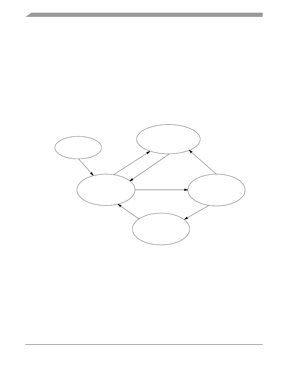
The lock detect function uses two counters. One is clocked by the reference and the other is clocked by the
PLL feedback. When the reference counter has counted N cycles, its count is compared to that of the
feedback counter. If the feedback counter has also counted N cycles, the process is repeated for N + K
counts. Then, if the two counters still match, the lock criteria is relaxed by 1/2 and the system is notified
that the PLL has achieved frequency lock.
After lock is detected, the lock circuit continues to monitor the reference and feedback frequencies using
the alternate count and compare process. If the counters do not match at any comparison time, then the
LOCK flag is cleared to indicate that the PLL has lost lock. At this point, the lock criteria is tightened and
the lock detect process is repeated.
The alternate count sequences prevent false lock detects due to frequency aliasing while the PLL tries to
lock. Alternating between tight and relaxed lock criteria prevents the lock detect function from randomly
toggling between locked and non-locked status due to phase sensitivities.
for detecting locked and non-locked conditions.
In external clock mode, the PLL is disabled and cannot lock.
Figure 9-6. Lock Detect Sequence
9.7.4.6
PLL Loss of Lock Conditions
Once the PLL acquires lock after reset, the LOCK and LOCKS flags are set. If the MFD is changed, or if
an unexpected loss of lock condition occurs, the LOCK and LOCKS flags are negated. While the PLL is
in the non-locked condition, the system clocks continue to be sourced from the PLL as the PLL attempts
to relock. Consequently, during the relocking process, the system clocks frequency is not well defined and
may exceed the maximum system frequency, violating the system clock timing specifications.
However, once the PLL has relocked, the LOCK flag is set. The LOCKS flag remains cleared if the loss
of lock is unexpected. The LOCKS flag is set when the loss of lock is caused by changing MFD. If the
PLL is intentionally disabled during stop mode, then after exit from stop mode, the LOCKS flag reflects
the value prior to entering stop mode once lock is regained.
Count N
Reference Cycles
and Compare
Number of Feedback
Cycles Elapsed
Start
with Tight Lock
Criteria
Reference Count
≠
Feedback Count
Loss of Lock Detected
Set Tight Lock Criteria
and Notify System of Loss
of Lock Condition
Count N + K
Reference Cycles
and Compare Number
of Feedback Cycles
Elapsed
Lock Detected.
Set Relaxed Lock
Condition and Notify
System of Lock
Condition
Reference Count
≠
Feedback Count
Reference Count =
Feedback Count = N
In Same Count/Compare Sequence
Reference Count =
Feedback Count = N + K
IN Same Count/Compare Sequence
MCF5282 and MCF5216 ColdFire Microcontroller User’s Manual, Rev. 3