12 i2c input/output timing specifications, 12 i, C input/output timing specifications – Motorola ColdFire MCF5281 User Manual
Page 704: Table 33-19 lists specifications for the i, C output timing parameters shown in figure 33-10
Electrical Characteristics
33-20
Freescale Semiconductor
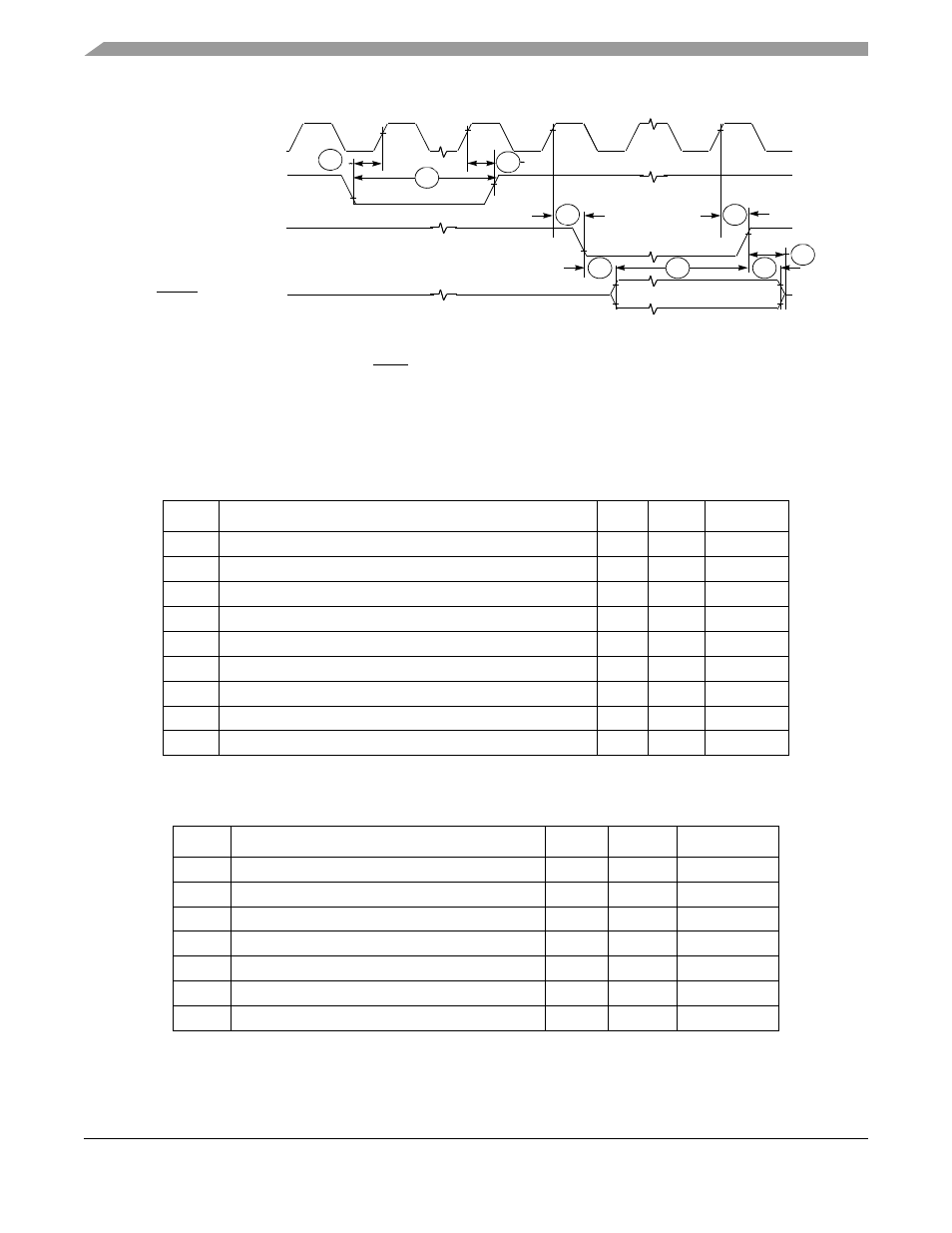
Figure 33-9. RSTI and Configuration Override Timing
33.12 I
2
C Input/Output Timing Specifications
lists specifications for the I
2
C input timing parameters shown in
lists specifications for the I
2
C output timing parameters shown in
.
Table 33-19. I
2
C Input Timing Specifications between SCL and SDA
Num
Characteristic
Min
Max
Units
I1
Start condition hold time
2
—
Bus clocks
I2
Clock low period
8
—
Bus clocks
I3
SCL/SDA rise time (V
IL
= 0.5 V to V
IH
= 2.4 V)
—
1
mS
I4
Data hold time
0
—
ns
I5
SCL/SDA fall time (V
IH
= 2.4 V to V
IL
= 0.5 V)
—
1
mS
I6
Clock high time
4
—
Bus clocks
I7
Data setup time
0
—
ns
I8
Start condition setup time (for repeated start condition only)
2
—
Bus clocks
I9
Stop condition setup time
2
—
Bus clocks
Table 33-20. I
2
C Output Timing Specifications between SCL and SDA
Num
Characteristic
Min
Max
Units
I1
1
Start condition hold time
6
—
Bus clocks
Clock low period
10
—
Bus clocks
I3
2
SCL/SDA rise time (V
IL
= 0.5 V to V
IH
= 2.4 V)
—
—
µS
Data hold time
7
—
Bus clocks
I5
3
SCL/SDA fall time (V
IH
= 2.4 V to V
IL
= 0.5 V)
—
3
ns
Clock high time
10
—
Bus clocks
Data setup time
2
—
Bus clocks
R1
R2
CLKOUT
RSTI
RSTO
R3
R4
R8
R7
R6
R5
Configuration Overrides:
R4
(RCON, Override pins)
MCF5282 and MCF5216 ColdFire Microcontroller User’s Manual, Rev. 3