5 control registers, 1 qadc control register 0 (qacr0), 5 control registers -10 – Motorola ColdFire MCF5281 User Manual
Page 548: 1 qadc control register 0 (qacr0) -10, Section 28.6.5, “control registers, Control registers
Queued Analog-to-Digital Converter (QADC)
28-10
Freescale Semiconductor
28.6.5
Control Registers
This subsection describes the QADC control registers.
28.6.5.1
QADC Control Register 0 (QACR0)
QACR0 establishes the QADC sampling clock (QCLK) with prescaler parameter fields and defines
whether external multiplexing is enabled. Typically, these bits are written once when the QADC is
initialized and not changed thereafter. The bits in this register are read anytime, write anytime (except
during stop mode).
7
6
5
4
3
2
1
0
Field
—
DDQB3
DDQB2
DDQB1
DDQB0
Reset
0000_0000
R/W
R
Address
IPSBAR + 0x19_0009
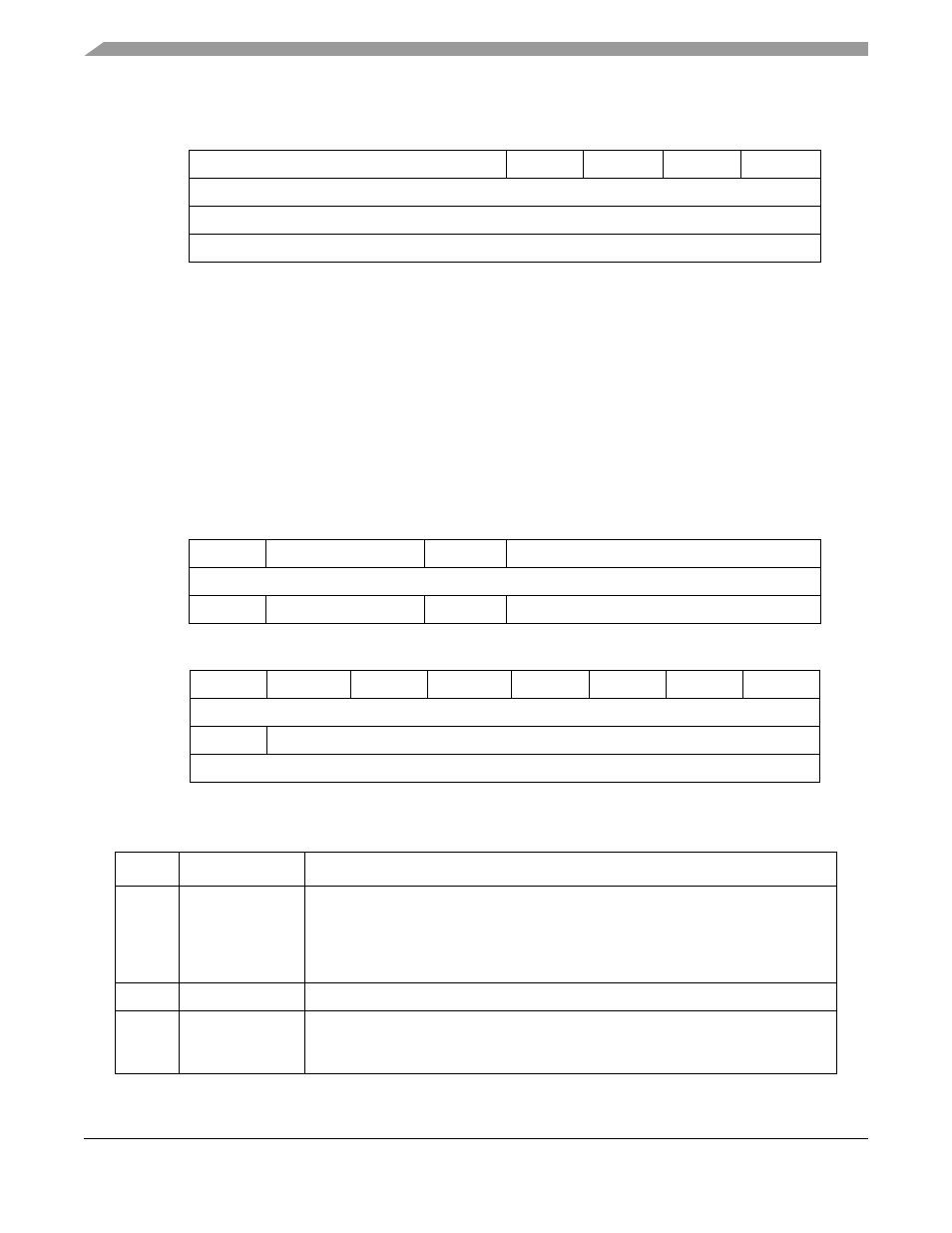
Figure 28-7. Port QB Data Direction Register (DDRQB)
15
14
13
12
11
8
Field
MUX
—
TRG
—
Reset
0000_0000
R/W:
R/W
R
R/W
R
7
6
5
4
3
2
1
0
Field
—
QPR6
QPR5
QPR4
QPR3
QPR2
QPR1
QPR0
Reset
0001_0011
R/W:
R
R/W
Address
IPSBAR + 0x19_000a, 0x19_000b
Figure 28-8. QADC Control Register 0 (QACR0)
Table 28-4. QACR0 Field Descriptions
Bit(s)
Name
Description
15
MUX
Externally multiplexed mode. Configures the QADC for operation in externally
multiplexed mode, which affects the interpretation of the channel numbers and forces
the MA[1:0] signals to be outputs.
1 Externally multiplexed, up to 18 possible channels
0 Internally multiplexed, up to 8 possible channels
14–13
—
Reserved, should be cleared.
12
TRG
Trigger assignment. Determines the queue assignment of the ETRIG[2:1] signals.
1 ETRIG1 triggers queue 2; ETRIG2 triggers queue 1.
0 ETRIG1 triggers queue 1; ETRIG2 triggers queue 2.
MCF5282 and MCF5216 ColdFire Microcontroller User’s Manual, Rev. 3