3 boot device selection, 4 output pad strength configuration, 5 clock mode selection – Motorola ColdFire MCF5281 User Manual
Page 537
Chip Configuration Module (CCM)
Freescale Semiconductor
27-9
NOTE
When Flash security is enabled, the chip will boot in single chip mode
regardless of the external reset configuration.
During reset, certain module configurations depend on whether emulation mode is active as determined
by the state of the internal emulation signal.
27.6.3
Boot Device Selection
During reset configuration, the CS0 chip select pin is optionally configured to select an external boot
device. In this case, the V (valid) bit in the CSMR0 register is ignored, and CS0 is enabled after reset. CS0
is asserted for the initial boot fetch accessed from address 0x0000_0000 for the Stack Pointer and address
0x0000_0004 for the program counter (PC). It is assumed that the reset vector loaded from address
0x0000_0004 causes the CPU to start executing from external memory space decoded by CS0.
27.6.4
Output Pad Strength Configuration
Output pad strength is determined during reset configuration as shown in
. Once reset is exited,
the output pad strength configuration can be changed by programming the LOAD bit of the chip
configuration register.
27.6.5
Clock Mode Selection
The clock mode is selected during reset by the CLKMOD pins and reflected in the PLLMODE, PLLSEL,
and PLLREF bits of SYNSR. After reset is exited, the clock mode cannot be changed.
summarizes clock mode selection during reset configuration.
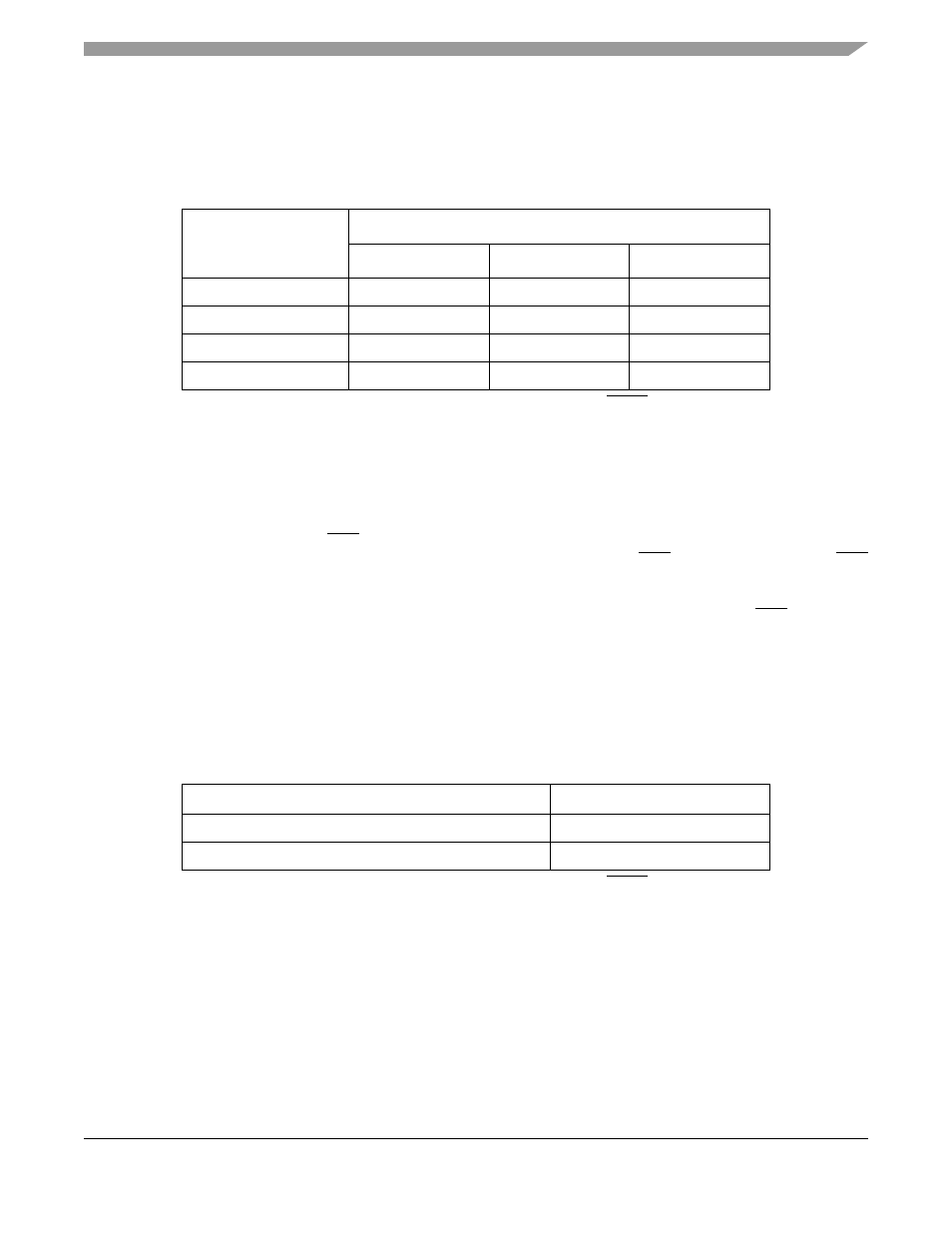
Table 27-9. Chip Configuration Mode Selection
1
1
Modifying the default configurations is possible only if the external RCON pin is asserted low.
Chip Configuration
Mode
CCR Register MODE Field
MODE2
MODE1
MODE0
Master mode
D26 driven high
D17 driven high
D16 driven high
Single-chip mode
D26 driven high
D17 driven high
D16 driven low
Reserved
D26 driven high
D17 driven low
D16 driven high
Reserved
D26 driven low
D17 don’t care
D16 don’t care
Table 27-10. Output Pad Driver Strength Selection
1
1
Modifying the default configurations is possible only if the external RCON pin is asserted low.
Optional Pin Function Selection
CCR Register LOAD Bit
Output pads configured for partial strength
D21 driven low
Output pads configured for full strength
D21 driven high
MCF5282 and MCF5216 ColdFire Microcontroller User’s Manual, Rev. 3